
Installation Instructions

Document No. A6V10425806
Installation Instructions
September 10, 2014
Siemens Industry, Inc.
Page 5 of 6
Wiring and Module Installation
WARNING
De-energize Class 1 circuits, tag and
lockout the breaker panel.
AVERTISSEMENT
Mettre les circuits de Classe 1 hors
tension, étiqueter et cadenasser le
disjoncteur.
1. De-energize Class 1 circuits, tag and lockout the
breaker panel.
2. Run conduit and pull wires into the panel.
- Leave enough wire for future changes or
additions
- Allow for full door swing clearance.
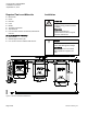
3. If it was removed, reinstall the DIN rail assembly.
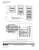
4. Snap Gamma modules onto the DIN rails.
- To make wiring separation easier and reduce
wiring terminations, use the top DIN rail for
low voltage devices that require a Data Rail
190/
x
2. See Figure 4 and Figure 5.
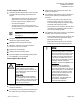
5. Route Class 1 wires through the knockouts that
you designated for Class 1 and terminate on the
Gamma devices.
6. Route Class 2 wires through knockouts on the
opposite side of the enclosure and terminate on
the Gamma devices.
7. Using wire ties, secure the Class 1 and Class 2
wires to opposite edges of the wire barrier to
maintain wire separation. See the magnified
section of Figure 5 for an example.
8. Reinstall the dead front.
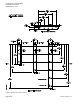
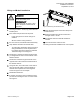
9. If needed, reverse the door by pulling the hinge
pin down and rotating the door out of the socket.
See Figure 3.
Figure 3: Reversing the Enclosure Door.
10. Place the panel layout sheet in the label pouch
inside the door.
11. Remove breaker panel tag and lockout and
energize Class 1 circuits.
12. Set Gamma devices in Manual Operation if
needed.
13. Close and lock the enclosure door.
The wiring and module installation are now complete.