
Installation Instructions

Document No. A6V10425806
Installation Instructions
September 10, 2014
Siemens Industry, Inc.
Page 3 of 6
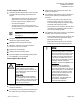
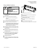
Positioning the Enclosure
1. Determine the mounting location of the enclosure
using the following spacing requirements and
Figure 1.
- Space between the face of the panel and an
obstruction in front of the panel must be at
least 11 inches (28 cm) to allow for door
removal at 40 degrees.
- To fully open the door, a clear space of at
least 28 inches (71 cm) is required from a wall
on the hinged side.
NOTE:
The enclosure door can be reversed.
See Figure 3.
2. Using the dimensions in Figure 1 for placement,
drill the two upper mounting holes.
3. Partially insert mounting bolts in holes.
4. Mount the enclosure to the wall. Check the
enclosure to be sure it is level.
5. Tighten the mounting bolts.
6. Drill the two lower mounting holes.
7. Insert and tighten the remaining mounting bolts.
The installation is now complete.
Removing the Knockouts
CAUTION
Separate knockouts should be used
for high voltage and low voltage
wiring. Leave at least a 2-inch (5 cm)
space between the Class 2 and other
wires in the panel.
ATTENTION
Utiliser des débouchures séparées
pour les lignes de haute et de basse
tension. Laisser un espace d’au moins
5 cm entre les lignes Classe 2 et les
autres fils dans l’armoire.
1. Open the enclosure door and remove the
enclosure dead front.
2. If necessary, remove the DIN rail assembly from
the enclosure by removing the mounting nuts.
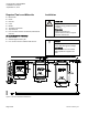
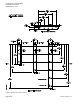
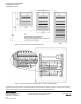
3. Determine the entry locations for wiring. See
Figure 2 and Figure 4.
4. The following steps apply to Class 1 lighting and
power circuits entering on the left side of the
enclosure.
- Punch one entrance on the left-most 1/2"
knockout (either on the top or side) for the
120V line voltage wiring to the power supply
and other 120V Gamma modules.
- Punch entrances as needed on the left side to
route wiring for the lighting power circuits to
and from the switching relays.
5. The following steps apply to Class 2 control wiring
for KNX, AUX, 0-10V, 24V, and DALI:
- Punch additional entrances as needed on the
enclosure side that is opposite the Class 1
lighting and power wiring.
- Ensure all Class 2 knockouts are at least 2
inches (5 cm) from other wiring knockouts.
NOTICE
Step 4 and Step 5 may be reversed so
that power wiring enters on the right
side of the enclosure. However, if data
rails are used, the order of the Data
Rail 190/
x
2 connector terminals must
be reversed to maintain the correct
polarity. For more information, see the
Data Rails 190 with Connector
Installation Instructions
(2515054115).
REMARQUE
Les étapes 4 et 5 peuvent être
inversées afin que l’alimentation
puisse être amené par le coté droit du
coffret. Cependant, en cas d’utilisation
de rails porteurs de données, l’ordre
des bornes de raccordement du rail
190/x2 doit être inversé pour
respecter la polarité. Pour plus
d’informations, voir
Data Rails 190
with Connector Installation
Instructions
(2515054115).