
Commissioning Instructions

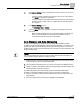


Table Of Contents
- Before You Begin
- Verifying Power
- Verifying Slave Mode Application Number
- Setting Controller Address
- Setting the Application
- Setting Display Units
- Testing the Operator Display Panel
- Setting Duct Area
- Setting Airflow Sensing Input
- Setting Flow Coefficients
- Automatic Calibration Option
- Setting Blank Display
- Setting Display Weight
- Setting Display Resolution
- Changing Exhaust Minimum
- Changing Exhaust Maximum
- Changing Face Velocity Setpoints and OCC Delay
- Setting Hi and Low Warn Limits
- Setting Hi and Low Alarm Limits
- Setting Alarm Timer
- Setting Emergency Setpoint
- Setting Emergency Timer
- Setting Remote Purge
- Fume Hood Specific Sash Setup and Calibration
- Setting External Face Area Input
- Setting Sash Area Alarms
- (Optional) Setting Damper Control — Application 6741
- Checkout of Damper — Application 6741
- (Optional) Setting Airflow Input Type
- (Optional) Calibrating the DP Transmitter without an Autozero Module
- (Optional) Calibrating with an Autozero Module
- AVS FAILMODE
- Setting Airflow Control — Application 6742
- Range of Airflow Control – Application 6742
- Configuring Airflow Control - Application 6742
- Setting AO2 Range
- Setting AO2 Voltage Minimum
- Start-up/Decommission Mode
- Loop Tuning Procedures
- Configuring BACnet Parameters
- Auto Discover and Auto Addressing
- Flashing Controller Firmware

Before You Begin
Flashing Controller Firmware
41
Siemens Industry, Inc. Start-up Procedures 140-1345
Restricted 2015-11-09
The Pre-Engineered Data file can be used in different ways. For example, you can
create a group or collection of information for every TEC. You can then assign the
correct group to the TEC based on the location as indicated by the job schedule. The
schedule will display the serial numbers for all TEC’s and the location where the TEC
was installed. The groups of data are set up for a specific location and you simply
select the correct group for the TEC that has the serial number associated with that
location.
You can also set up groups that contain information that must be set in multiple TEC’s.
Select all TEC’s that need the specific data and assign the ID.
Sample .csv file:
IDENTIFIER,FIELDID,FIELDVAL
Building100_TEC_VAV001,ObjectName,VAV in Building 100
Building100_TEC_VAV001,Instance,5400
Flashing Controller Firmware
NOTE:
When re-loading/flashing firmware, existing PPCL may no longer function correctly.
FLT Procedure
Use the Firmware Loading Tool (FLT) for this procedure.
1. Connect to the RTS port of the PTEC.
2. Set Communications to 38400 baud.
3. Click the Identify button.
4. Browse to the folder where the new firmware is saved.
5. Double-click the firmware file and then click Load.
WCIS Procedure
1. Connect to the RTS port of the PTEC.
2. From the Device menu, select Load TEC Firmware.
The Load TEC Firmware dialog box displays.
3. Click the Browse button.
4. Browse to the folder where the new firmware is saved.
5. Double-click the firmware file and then click Load.