User Guide control KVM series3-1621 Keyboard/Video/Mouse Switch 590-591-501B English 3
USA Notification Warning: Changes or modifications to this unit not expressly approved by the party responsible for compliance could void the user’s authority to operate the equipment. Note: This equipment has been tested and found to comply with the limits for a Class A digital device, pursuant to Part 15 of the FCC Rules. These limits are designed to provide reasonable protection against harmful interference when the equipment is operated in a commercial environment.
KVM s3-1621 and s3-1641 User Guide Edition July 2007
Comments... Suggestions... Corrections The User Documentation Department would like to know your opinion of this manual. Your feedback helps us optimize our documentation to suit your individual needs. Fax forms for sending us your comments are included in the back of the manual. There you will also find the addresses of the relevant User Documentation Department.
Contents Contents 1 1.1 1.2 1.3 1.3.1 1.3.2 1.3.3 1.3.3.1 1.3.3.2 1.3.4 1.3.5 1.3.6 1.3.7 1.3.8 2 2.1 2.1.1 2.1.2 2.2 2.3 2.3.1 2.4 2.4.1 2.4.2 2.5 2.5.1 2.5.2 2.6 2.7 2.8 2.9 2.9.1 2.10 3 3.1 3.2 590-591-609B Product overview .................................................................................... 1 Glossary .................................................................................................... 1 Notational Conventions ............................................................
Contents 3.3 3.4 3.5 3.6 3.7 3.8 3.9 3.9.1 3.9.2 3.9.2.1 3.9.2.2 3.9.3 3.9.3.1 3.9.3.2 3.9.3.3 3.9.4 3.9.5 3.9.6 3.9.7 3.9.7.1 3.9.7.2 3.9.7.3 3.9.7.4 3.9.7.5 3.10 3.11 3.11.1 3.11.2 3.11.3 3.11.4 3.11.5 3.11.5.1 3.11.5.2 3.11.6 3.12 3.12.1 3.12.2 3.12.3 3.12.4 3.13 Setting a screen delay ............................................................................. 19 Connecting a user to a target device.......................................................
Contents 4 4.1 4.1.1 4.1.2 4.1.3 4.1.3.1 4.1.3.2 4.1.3.3 4.1.3.4 4.1.3.5 4.1.3.6 5.1 5.1.1 5.1.2 5.1.3 5.2 5.2.1 5.2.2 5.2.2.1 5.2.2.2 5.3 5.3.1 5.3.2 5.3.3 5.4 5.5 5.5.1 590-591-609B Computer terminal operations ............................................................. 43 The Console menu .................................................................................. 43 Configuring network settings ...................................................................
Contents 590-591-609B
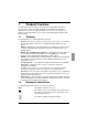
1 Product Overview The KVM s3-1621and the KVM s3-1641 appliances integrate digital and analog keyboard, video, and mouse (KVM) switching technology with advanced cable management, access for two or four simultaneous users, and a user interface. The appliances have USB and PS/2® ports on the rear panel that support all major target device platforms. 1.1 Glossary The following terms are used throughout this document: • ACI Port - ACI stands for “analog console interface”.
Product Overview Title This indicates information, which if not heeded, may jeopardize your health, the functioning of your system, or the security of your data. This indicates a step that you have to perform. - and • These characters symbolize itemized lists. Bold monospace font This indicates user inputs in examples. 1.3 Features and benefits The KVM s3-1621 and KVM s3-1641 appliances are rack-mountable KVM switches that are configurable for analog (local) or digital (remote) connectivity.
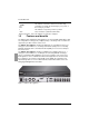
KVM-IA Intelligent Adapters Figure 2: KVM s3-1641 appliance The KVM s3-1621 and KVM s3-1641 appliances have user peripheral ports for PS/2® and USB keyboards and mice. Additionally, virtual media, such as generic removable media and CD drives, can be connected to any one of four USB ports. The KVM s3-1621 and KVM s3-1641 appliances work over standard LAN connections.
Product Overview manipulation. The KVM-IA is powered directly from the target device and provides Keep Alive functionality when the KVM s3-1621 or KVM s3-1641 appliance is not turned on. The KVM-IAs enable direct KVM connectivity to target devices that are attached to the KVM s3-1621 or KVM s3-1641 appliance. Each KVM s3-1621 and KVM s3-1641 appliance has 16 ARI ports for connecting KVM-IAs.
Flash upgradability depending upon the length of cable that is separating the KVM s3-1621 or KVM s3-1641 appliance and target devices. 1.3.5 Flash upgradability Upgrade the KVM s3-1621 and KVM s3-1641 appliances at any time through the network port to ensure the KVM s3-1621 or KVM s3-1641 appliance is always running the most current available version. See Appendix 5.1 on page 47 for detailed information. 1.3.
Product Overview Figure 4 illustrates a typical KVM s3-1621 or KVM s3-1641 appliance configuration.
2 Installation The KVM s3-1621 and KVM s3-1641 appliances require connectivity to a computer running the KVM s3 Client. Use the KVM s3 Client to view and control target devices (one at a time) attached to a KVM s3-1621 or KVM s3-1641 appliance. The analog port does not require the KVM s3 Client for operation. The analog port uses OSCAR for the Fujitsu Siemens graphical user interface. For more information, see Chapter 3, “Basic operations”, beginning on page 17, or the KVM s3 Client User Guide.
Installation Figure 6 illustrates one possible configuration for the KVM s3-1621 or KVM s3-1641 appliance. Rack of target servers KVM s3-1621 or KVM s3-1641 appliance Ethernet Digital user Analog user Digital user Figure 6: Example KVM s3-1621 or KVM s3-1641 appliance configuration 2.1.2 Setting up the network The KVM s3-1621 and KVM s3-1641 appliances and KVM-IAs use IP addresses to uniquely identify the appliances and the target devices.
Required items 2.2 Required items Before you install a KVM s3-1621 or KVM s3-1641 appliance, make sure that you have all the required items.
Installation • • • • • • • • • the applicable section in the troubleshooting guide or contact the trained service provider. Use the KVM s3-1621 and KVM s3-1641 appliances only with approved equipment. Operate the KVM s3-1621 or KVM s3-1641 appliance only from the type of external power source that is indicated on the electrical ratings label. If you are not sure of the type of power source that is required, consult the service provider or local power company.
Installing a KVM appliance in the rack mounting space • • • Mechanical loading: Avoid a potentially hazardous condition caused by uneven mechanical loading by carefully mounting the equipment in the rack. Circuit overloading: Consider the connection of the equipment to the supply circuit and the effect that overloading of circuits might have on overcurrent protection and supply wiring. Observe equipment nameplate ratings for maximum current.
Installation 2.5 Turn off the target devices that are part of the switching system. Connect one end of the power cord to the rear of the KVM s3-1621 or KVM s3-1641 appliance, and connect the other end to an ac power source. Connect a VGA monitor and either PS/2 or USB keyboard and mouse cables into the labeled KVM s3-1621 or KVM s3-1641 appliance ports. You must install both a keyboard and mouse on the local ports or the keyboard will not initialize correctly.
Verifying Ethernet connections 2.6 Verifying Ethernet connections The Ethernet connection has two LEDs. The green LED on the right is the Link indicator. It is lit when a valid connection to the network is established, and it flashes when there is activity on the port. The amber/green LED on the left indicates that you are communicating at 100 Mbps (amber) or 1000 Mbps (green) when using the Ethernet connection. 2.
Installation • Attach one end of a Cat 5 cable directly to the Analog Console Interface (ACI) port on the tiered appliance. (If you are unsure if the appliance being tiered has an ACI port, please consult the Installer/User guide for the tiered appliance.) Connect the other end of the Cat 5 cable to any available ARI port on the rear of the KVM s3-1621 or KVM s3-1641 appliance.
Setting up the KVM s3-1621 and KVM s3-1641 appliances 2.10 Setting up the KVM s3-1621 and KVM s3-1641 appliances With the KVM s3-1621 and KVM s3-1641 appliances, you can auto detect and configure each port on the appliance. Chapter 3 provides detailed instructions on naming customization and OSCAR interface setup and configuration.
Installation 16 590-591-609B
3 Basic operations 3.1 Controlling the switching system from the analog port The KVM s3-1621 and KVM s3-1641 appliances include ports on the rear panel that you can use to connect a keyboard, monitor, and mouse to the appliances for direct analog access. The KVM s3-1621 and KVM s3-1641 appliances use the OSCAR interface, which has intuitive menus to configure the switching system and select target devices. Switches can be identified by customizable names. 3.
Basic operations The Main window lists the target devices in the switching system. You can order the list by target device names, EID numbers, or port numbers by clicking the Name, EID, or Port button. The Port column indicates the ARI port to which each target device is connected. If an earlier appliance model is connected to a KVM s3-1621 or KVM s3-1641 appliance, the ARI port number is shown first, followed by the number of the appliance port to which the target device is connected.
Setting a screen delay 3.3 Setting a screen delay You can specify the length of time that elapses between when Print Screen is pressed and when the OSCAR interface starts. Press Print Screen to start the OSCAR interface. In the Main window, click Setup - Menu. In the Screen Delay Time field, type the number of seconds that you want to elapse between when Print Screen is pressed and when the OSCAR interface starts. 3.
Basic operations 3.7 Using the OSCAR interface Table 3 describes the keys, key combinations, and mouse actions that you can use in the OSCAR interface. Two or more key names or mouse actions that are separated by commas indicate a sequence of actions. Two or more key names or mouse actions that are separated by a plus sign (+) indicate a combination of actions; that is, they are performed simultaneously.
Connecting local virtual media Key, key combination, Result or mouse action Print Screen, Backspace Return to the previously selected target device. Print Screen, Alt+0 Disconnect the user from the selected target device. Note that the zero must be typed on the main keyboard, not the numeric keypad. Print Screen, Pause Start the screen saver immediately and lock the user, if it is password-protected. Up Arrow or Down Arrow Move the cursor from line to line in a list.
Basic operations Select one or more of the following check boxes: • Locked - Select this check box to specify that when the user is disconnected from a target device, the virtual media is also disconnected. -or• Reserve - Select this check box to specify that the virtual media connection can be accessed only by your user name and that no other user can connect to that target device. If both Locked and Reserved are selected, the session will be reserved.
Assigning target device names Table 4 describes the options in the Setup window. Option Purpose Menu Order the list of target devices by target device name, EID number, or port number. Set a screen delay to specify the length of time that elapses between when Print Screen is pressed and when the OSCAR interface starts. Security Set passwords to restrict access to the target devices. Enable the screen saver. Flag Change the display properties including timing, color, and location of the status flag.
Basic operations Figure 10: Names window If new KVM-IAs are discovered by the KVM s3-1621 or KVM s3-1641 appliance, the onscreen list will automatically be updated. The mouse cursor will change into an hourglass during the update. No mouse or keyboard input will be accepted until the list update is complete. In the Names window, select a target device name or port number and click Modify. The Name Modify window opens.
Assigning appliance and device types Type a name in the New Name field. Names of target devices can be up to 15 characters long. Valid characters are A through Z, a through z, 0 through 9, space, and hyphen. Click OK to transfer the new name to the Names window. The selection is not saved until you click OK in the Names window. Repeat steps 1 to 3 for each target device in the switching system.
Basic operations For example, if the earlier appliance model is connected to ARI port 6, the earlier appliance model port is listed as 06, and the target devices that are under it are numbered sequentially as 06-01, 06-02, and so on. 3.9.2.2 Assigning a switch type In the Devices window, select the port number. Click Modify. The Device Modify window opens. Figure 13: Device Modify window Select or type the number of ports that are supported by the tiered earlier appliance model and click OK.
Changing the display behavior Figure 14: Menu window 3.9.3.1 Selecting the order of the target devices Click one of the following buttons: • Select Name to list the target devices alphabetically by target device name. -or• Select EID to list the target devices numerically by EID number. -or• Select Port to list the target devices numerically by port number. Click OK. 3.9.3.
Basic operations 3.9.4 Selecting the display language Use the Setup window to change the display language for the OSCAR interface. Figure 15: Language window Press Print Screen to start the OSCAR interface. The Main window opens. Click Setup - Language. The Language window opens. In the Language window, select the language and click OK. 3.9.
Controlling the status flag Click Setup - Flag. the Flag Setup window opens. Figure 16: Flag Setup window Set one or more of the following settings: • Select Name or EID to specify the information that is displayed in the flag. • Select Displayed to display the flag all the time, or select Timed to display the flag for only 5 seconds after you select a target device. • In the Display color section, select the flag color.
Basic operations 3.9.6 Setting the keyboard country code By default, the KVM s3-1621 and KVM s3-1641 appliances send the US keyboard country code to USB cables attached to target devices, and the code is applied to the target devices when they are turned on or rebooted. Codes are then stored in the KVM-IA. Using a keyboard code that supports a language different from that of the KVM s3-1621 and KVM s3-1641 appliance firmware will cause incorrect keyboard mapping.
Setting KVM s3-1621 and KVM s3-1641 appliance security 3.9.7 Setting KVM s3-1621 and KVM s3-1641 appliance security You can enable a screen saver to start if the user remains unused for a specified length of time. When the screen saver starts, the user is disconnected from any target device to which it was connected. The screen saver stops when you press any key or move the mouse. Press Print Screen and press Pause to immediately start the screen saver.
Basic operations 3.9.7.4 Recovering a password Power cycle the appliance (this will take about 45 seconds) At the “Free” prompt, press Print Screen. The Authorize window appears. Click the Forgot Password button at the bottom of the Authorize window.
Managing target device tasks using the OSCAR interface • If you enter a value of 5 to 120 seconds, the first user will be warned and will be allowed to continue using the target device for up to the amount of time in the Timeout Seconds field. The session will be preempted when the user clicks OK, or when the specified time elapses. Click OK to save the settings. Figure 19: Preempt window 3.
Basic operations 3.11.1 Accessing the Commands window Press Print Screen. The Main window opens. Click Commands. The Commands window opens. Figure 20: Commands window 3.11.2 Displaying version information You can use the OSCAR interface to view the version of the KVM s3-1621 or KVM s31641 appliance and the KVM-IA firmware you are using. For more information, see Appendix 5.1 on page 47. Press Print Screen. The Main window opens. Click Commands - Display Versions. The Version window opens.
Upgrading the firmware Figure 21: Version window Click the KVM-IA button to view individual KVM-IA version information. The KVMIA Select window opens. Select a KVM-IA to view and click the Version button. The KVM-IA Version window opens. For more information about loading firmware, see Appendix 5.1 on page 47. Click X to close the KVM-IA Version window. 3.11.
Basic operations Figure 22: Upgrade window Press Print Screen. The Main window opens. Click Commands - Display Versions - Upgrade. The Upgrade window opens. Click Upgrade. A Warning window opens. Clicking OK opens the Upgrade Process window. The progress of the upgrade is indicated in the Programmed field. 3.11.4 Viewing the display configuration Use the Display configuration window to view the current configuration of the switching system. Click Commands - Display config.
Viewing and disconnecting user connections Figure 23: User Status window 3.11.5.2 Disconnecting a user From the User Status window, click the letter that corresponds to the user to disconnect. The Disconnect window opens. Complete one of the following steps: • Click OK to disconnect the user and return to the User Status window. -or• Click X or press Escape to exit the window without disconnecting a user.
Basic operations Figure 24: Disconnect window 3.11.6 Resetting the keyboard and mouse values You can reset the keyboard and mouse by clicking Commands - Device Reset. If the keyboard or mouse is still not responding, you might be able to re-establish operation of these peripheral switches by issuing a Reset command for the mouse and keyboard settings on the target server.
Scanning the switching system 3.12 Scanning the switching system In scan mode, the KVM s3-1621 and KVM s3-1641 appliances automatically scan from port to port (target device to target device). Use scan mode to monitor the activity of up to 16 target devices, and to specify which target devices to scan and the number of seconds that each target device will be visible. The scanning order is determined by placement of the target device in the list, which is always shown in scanning order.
Basic operations 3.12.2 Removing a target device from the scan list To select a target device to be removed from the scan list, complete one of the following steps: • In the Scan window, clear the check box next to the target device to be removed. -or• Double-click on the target device name or port. -or• Press Shift + Delete to remove the selected target device and all entries below it. -or• Click the Clear button to remove all target devices from the scan list. Click OK. 3.12.
Canceling scan mode 3.12.4 • • Canceling scan mode If the OSCAR interface is open, select a target device. -orIf the OSCAR interface is not open, move the mouse or press any key on the keyboard to stop scanning at the currently selected target device. 3.13 Running switching system diagnostic tests You can validate the integrity of the switching system through the Run Diagnostics command.
Basic operations Table 7 details each of the tests. Test Description Firmware CRCs Reports on the condition of the appliance RAM. Remote User Video Reports on the condition of the remote user video. LAN connection Reports on the condition of the LAN connection. On-line KVM-IAs Indicates the total number of currently connected and turned on KVM-IAs. Offline KVM-IAs Indicates the number of KVM-IAs that have been connected successfully in the past and are turned off.
4 Computer terminal operations 4.1 The Console menu Each KVM s3-1621 and KVM s3-1641 appliance can be configured at the appliance level through the Console menu interface accessed through the configuration port on the rear panel of the KVM s3-1621 or KVM s3-1641 appliance. All terminal commands are accessed through a terminal or computer running terminal emulation software. This is not the best method for setting options for the KVM s3-1621 and KVM s3-1641 appliances.
Computer terminal operations A static IP address can be used to provide a user-defined IP address, netmask, and default gateway for the KVM s3-1621 and KVM s3-1641 appliances. Use a static IP address for ease of configuration. DHCP is a protocol that automates the configuration of TCP/IP-enabled computers. When DHCP is selected, the IP Address, Netmask, and Default Gateway settings are automatically assigned to the KVM s3-1621 and KVM s3-1641 appliances and cannot be modified by a user.
Other Console Main menu options 4.1.3 Other Console Main menu options Besides the Network Configuration option, the Console Main menu of the KVM s3-1621 and KVM s3-1641 appliances have the following menu items: Security Configuration, Firmware Management, Enable Debug Messages, Restore Factory Defaults, Reset Device, and Exit. Each is discussed in the following section. 4.1.3.
Computer terminal operations 46 590-591-609B
5 Appendices 5.1 Flash upgrades You can use the KVM s3-1621 and KVM s3-1641 appliance Flash upgrade feature to update the appliances with the latest firmware available. This update can be performed using the KVM s3 Client or using a Trivial File Transfer Protocol (TFTP) target server. After the Flash memory is reprogrammed with the upgrade, the KVM s3-1621 or KVM s3-1641 appliance performs a soft reset, which terminates all KVM-IA sessions.
Appendices 5.1.3 Repairing damaged firmware In the rare case that the firmware is damaged after a firmware upgrade (which might happen if the KVM s3-1621 or KVM s3-1641 appliance is turned off and turned on during the upgrade process), the KVM s3-1621 or KVM s3-1641 appliance will remain in boot mode.
Booting a computer using virtual memory 5.2.2 Booting a computer using virtual memory In many cases the virtual media feature can boot an attached computer from a device attached to the USB port on the KVM s3-1621 or KVM s3-1641 appliance. Most computers with a USB port can use virtual media; however, limitations in some USB media devices and the BIOS of some computers might prevent the computer from booting from a USB device attached to the KVM s3-1621 or KVM s3-1641 appliance.
Appendices 5.2.2.2 Virtual media restrictions The following list specifies restrictions for using virtual media: • The KVM s3-1621 and KVM s3-1641 virtual media appliances support only the connection of USB 2.0 diskette drives, Flash drives, and CD drives. • The KVM s3 Client supports only mapping of USB 2.0 and USB 1.1 diskette drives and Flash drives connected to the client computer. 5.3 UTP cabling The following information is intended to brief you on various aspects of connection media.
Wiring standards 5.3.2 Wiring standards There are two supported wiring standards for 8-conductor (4-pair) RJ-45 terminated UTP cable: EIA/TIA 568A and B. These standards apply to installations utilizing Cat 5, 5E, and 6 cable specifications. The switching system supports either of these wiring standards. Refer to the following table for details.
Appendices • Always install jacks to prevent dust and other contaminants from settling on the contacts. The contacts of the jack should face up on the flush mounted plates, or left, right, or down on surface mount boxes. Always leave extra slack in the cables, neatly coiled in the ceiling or nearest concealed location. Leave at least five feet at the work outlet side and 10 feet at the patch panel side. Choose either 568A or 568B wiring standard before beginning.
Technical specifications Local Port Number 1 Type USB, PS/2, and VGA Connectors PS/2 miniDIN, 15 pin D, RJ-45 USB Switch Port Number 4 Type USB 2.0 Dimensions Height x Width x Depth 1.72 in. x 17.00 in.x 10.98; 1-U form factor (4.37 cm x 43.18 cm x 27.98) Weight 7.3 lbs (3.31 kg) without cables Power Supply Heat dissipation 92 BTU/Hr Airflow 8 CFM Power consumption 12.
Appendices 5.5 Technical Support Our Technical Support staff is ready to assist you with any installation or operating issues you encounter with your Fujitsu Siemens product. If an issue should develop, follow the steps below for the fastest possible service: Check the pertinent section of this manual to see if the issue can be resolved by following the procedures outlined. Check our web site at http://www.fujitsu-siemens.com/support/ and click on Services & Support.
KVM s3-1621 und s3-1641 Bedienungsanleitung Ausgabe Juli 2007
Kommentare… Vorschläge… Verbesserungen Unsere Abteilung für technische Dokumentation würde gerne Ihre Meinung zu diesem Handbuch erfahren. Ihr Feedback hilft uns, unsere Dokumentation zu optimieren, indem Ihre individuellen Anforderungen erfüllt werden. Sie finden hinten im Handbuch FaxFormulare, mit denen Sie uns Ihre Kommentare zuschicken können. Dort befindet sich auch die Adresse der entsprechenden Abteilung für technische Dokumentation.
Inhalt Inhalt 1 1.1 1.2 1.3 1.3.1 1.3.2 1.3.3 1.3.3.1 1.3.3.2 1.3.4 1.3.5 1.3.6 1.3.7 1.3.8 2 2.1 2.1.1 2.1.2 2.2 2.3 2.3.1 2.4 2.4.1 2.4.2 2.5 2.5.1 2.5.2 2.6 2.7 2.8 2.9 2.9.1 2.10 3 3.1 3.2 3.3 590-591-609B Produktüberblick ..................................................................................... 1 Glossar ...................................................................................................... 1 Darstellungskonventionen .........................................................
Inhalt 3.4 3.5 3.6 3.7 3.8 3.9 3.9.1 3.9.2 3.9.2.1 3.9.2.2 3.9.3 3.9.3.1 3.9.3.2 3.9.3.3 3.9.4 3.9.5 3.9.6 3.9.7 3.9.7.1 3.9.7.2 3.9.7.3 3.9.7.4 3.9.7.5 3.10 3.11 3.11.1 3.11.2 3.11.3 3.11.4 3.11.5 3.11.5.1 3.11.5.2 3.11.6 3.12 3.12.1 3.12.2 3.12.3 3.12.4 Verbinden eines Benutzers mit einem Zielgerät...................................... 19 Auswählen des vorherigen Zielgeräts ..................................................... 20 Trennen der Verbindung zwischen Benutzer und Zielgerät ....................
Inhalt 3.13 4 4.1 4.1.1 4.1.2 4.1.3 4.1.3.1 4.1.3.2 4.1.3.3 4.1.3.4 4.1.3.5 4.1.3.6 5.1 5.1.1 5.1.2 5.1.3 5.2 5.2.1 5.2.2 5.2.2.1 5.2.2.2 5.3 5.3.1 5.3.2 5.3.3 5.4 5.5 5.5.1 590-591-609B Diagnosetest des Switching-Systems ..................................................... 44 Terminalbetrieb des Computers .......................................................... 47 Konsolenmenü ........................................................................................
Inhalt 590-591-609B
1 Produktüberblick Die KVM s3-1621- und KVM s3-1641-Einheiten kombinieren digitale und analoge KVMSwitching-Technologie (Keyboard, Video, Maus) mit ausgereiftem Kabelmanagement, Zugriff für zwei bis vier Benutzer gleichzeitig und einer intuitiven Benutzeroberfläche. Die Einheiten verfügen an der Rückseite des Geräts über USB- und PS/2®-Ports, die alle gängigen Zielgeräte-Plattformen unterstützen. 1.
Produktüberblick Verweist auf zusätzliche Informationen und Tipps. Titel Verweist auf Informationen, die bei Nichtbeachtung Ihre Gesundheit, die Funktionsfähigkeit des Systems oder die Datensicherheit beeinträchtigen können. Verweist auf einen Schritt, den Sie ausführen müssen. - und • Diese Zeichen weisen auf Gliederungen hin. Bold monospace font Gibt Eingaben des Benutzers in Beispielen an. 1.
KVM-IA - Intelligente Adapter Abbildung 2: KVM s3-1641-Einheit Die KVM s3-1621- und KVM s3-1641-Einheiten verfügen über Benutzer-PeripheriePorts für PS/2®- und USB-Tastaturen und -Mäuse. Darüber hinaus können Virtual Media-Geräte wie z. B. generische Wechseldatenträger und CD-Laufwerke an jeden der vier USB-Ports angeschlossen werden. Die KVM s3-1621- und KVM s3-1641-Einheiten arbeiten über standardmäßige LANVerbindungen.
Produktüberblick und dauerhaft gespeichert werden. Diese integrierte „Intelligenz“ verbessert die Sicherheit und verhindert einen unautorisierten Zugriff auf ein Zielgerät durch Kabelmanipulation. Der KVM-IA wird direkt vom Zielgerät mit Strom versorgt und verfügt selbst bei ausgeschalteter KVM s3-1621- oder KVM s3-1641-Einheit über eine „Keep Alive“-Funktionalität. Die KVM-IAs ermöglichen direkte KVM-Konnektivität mit Zielgeräten, die an die KVM s3-1621- oder KVM s3-1641-Einheit angeschlossen sind.
Video 1.3.3.2 Betriebsmodi Die OSCAR-Benutzeroberfläche bietet verschiedene Betriebsmodi für die Systemadministration der KVM s3-1621 und KVM s3-1641-Einheiten. Mithilfe dieser Modi (Scannen, Switching und Teilen) können Sie die Switching-Aktivitäten verwalten. Weitere Informationen finden Sie im auf Seite 17 beginnenden Kapitel 3„Normalbetrieb“. 1.3.4 Video Die KVM s3-1621- und KVM s3-1641-Einheiten ermöglichen optimale Bildschirmauflösungen für analoges VGA-, SVGA- und XGA-Video.
Produktüberblick Abbildung 4 zeigt eine typische KVM s3-1621- oder KVM s3-1641Einheitenkonfiguration .
2 Installation Die KVM s3-1621- und KVM s3-1641-Einheiten müssen mit einem Computer verbunden sein, auf dem der KVM s3 Client ausgeführt wird. Mit dem KVM s3 Client können Sie Zielgeräte, die an eine KVM s3-1621- oder KVM s3-1641-Einheit angeschlossen sind, anzeigen und steuern (ein Gerät nach dem anderen). Der KVM s3 Client ist für den Betrieb des Analogports nicht notwendig. Der Analogport verwendet OSCAR als grafische Benutzeroberfläche von Fujitsu Siemens.
Einrichten des Netzwerks Installation Abbildung 6 zeigt eine mögliche Konfiguration der KVM s3-1621- oder KVM s3-1641Einheit. Rack mit Zielservern CAT 5-Verbindung KVM-Verbindung mit dem Switch Remote-IP-Verbindung KVM s3-1621- oder KVM s3-1641Einheit Ethernet Digitaler Benutzer Analoger Benutzer Digitaler Benutzer Abbildung 6: Beispielkonfiguration einer KVM s3-1621- oder KVM s3-1641-Einheit 2.1.
Installation 2.2 Erforderliche Komponenten Erforderliche Komponenten Stellen Sie vor der Installation einer KVM s3-1621- oder KVM s3-1641-Einheit sicher, dass alle erforderlichen Komponenten vorhanden sind.
Allgemeine Sicherheitshinweise • • • • • • • • • • • 10 Installation Stellen Sie die KVM s3-1621- und KVM s3-1641-Einheiten in sicherer Entfernung von Heizkörpern und Wärmequellen auf. Achten Sie darauf, dass die Lüfteröffnungen nicht blockiert sind. Achten Sie darauf, die Komponenten der KVM s3-1621- und KVM s3-1641Einheiten nicht mit Nahrungsmitteln oder Flüssigkeiten zu verunreinigen und betreiben Sie die KVM s3-1621- und KVM s3-1641-Einheiten nicht in feuchter Umgebung.
Installation 2.4 Rackbefestigung einer KVM-Einheit Rackbefestigung einer KVM-Einheit Vor der Installation der KVM s3-1621- oder KVM s3-1641-Einheit und anderer Komponenten im Rack (falls noch nicht installiert) muss das Rack am vorgesehenen Standort stabilisiert werden. Bestücken Sie das Rack von unten nach oben mit Komponenten. Vermeiden Sie eine ungleichmäßige Belastung und achten Sie darauf, dass das Rack nicht überladen wird. 2.4.
Anschließen der KVM-Einheiten-Hardware Installation Bauen Sie die KVM s3-1621- oder KVM s3-1641-Einheit in das Rack ein, indem Sie die Bohrungen in der kurzen Seite der Befestigungshalterung an einem entsprechenden Satz passender Bohrungen am Rack ausrichten. Führen Sie dann die Kombinations-Kreuzschlitzschrauben durch die Schlitze der Befestigungshalterung und die Bohrungen in der Befestigungsstrebe und danach in die Käfig- oder Schnappmuttern ein.
Installation Anschließen eines KVM-IA an ein Zielgerät Wenn Sie die KVM s3-1621- oder KVM s3-1641-Einheiten über die Konsolenmenüs konfigurieren, schließen Sie einen Computer, auf dem Terminal-Emulationssoftware ausgeführt wird, mit dem mitgelieferten seriellen Durchgangskabel an den IOIOIPort an der Rückseite der Einheit an. Das Terminal muss wie folgt eingestellt sein: 9600 Bit pro Sekunde (bps), 8 Bit, 1 Stoppbit, keine Parität und keine Flusskontrolle.
Anpassen der Mauseinstellungen 2.8 Installation Anpassen der Mauseinstellungen Bevor ein Computer, der an die KVM s3-1621- oder KVM s3-1641-Einheit angeschlossen ist, für die Steuerung durch einen Remote-Benutzer verwendet werden kann, muss die Mausgeschwindigkeit des Zielgeräts eingestellt und die Mausbeschleunigung deaktiviert werden.
Installation Anschließen eines nicht kompatiblen Switch-Modells Schalten Sie die mit den gestuften Einheiten verbundenen Zielgeräte aus und wieder ein und beachten Sie dabei die geltenden Anweisungen. Schalten Sie die gestuften Einheiten aus und wieder ein, damit der lokale Port den KVM-IA erkennt. Wiederholen Sie die Schritte 1 bis 5 für alle gestuften Einheiten, die an das Switching-System angeschlossen werden sollen. Das Switching-System führt die beiden Einheiten automatisch zusammen.
Einrichten der KVM s3-1621- und KVM s3-1641-Einheiten Installation Wählen Sie in der OSCAR-Benutzeroberfläche das Gerät aus, das mit der KVM s31621- oder KVM s3-1641-Einheit verwendet werden soll. 2.10 Einrichten der KVM s3-1621- und KVM s3-1641-Einheiten Die KVM s3-1621- und KVM s3-1641-Einheiten bieten Ihnen die Möglichkeit, jeden Port der Einheit automatisch erkennen und konfigurieren zu lassen.
3 Normalbetrieb 3.1 Steuern des Switching-Systems über den Analogport Die KVM s3-1621- und KVM s3-1641-Einheiten verfügen auf der Rückseite über Ports, an die Sie zum direkten analogen Zugriff Tastatur, Bildschirm und Maus anschließen können. Die KVM s3-1621- und KVM s3-1641-Einheiten verwenden die OSCARBenutzeroberfläche mit intuitiven Menüs zur Konfiguration des Switching-Systems und zur Auswahl der Zielgeräte. Switches können durch benutzerdefinierte Namen identifiziert werden. 3.
Aufrufen der OSCAR-Benutzeroberfläche Normalbetrieb Abbildung 8: Beispiel eines Hauptmenüs Das Hauptmenü listet die Zielgeräte im Switching-System auf. Sie können die Liste der Zielgeräte nach Namen, EID- oder Port-Nummern sortieren, indem Sie auf die entsprechende Schaltfläche Name, EID oder Port klicken. Die Spalte Port zeigt den ARI-Port, an den das jeweilige Zielgerät angeschlossen ist.
Normalbetrieb Einstellen der Zeitverzögerung Das Zielgerät ist über eine ältere Einheit gestuft. Die ältere Einheit ist offline oder wird nicht mit Strom versorgt. Der KVM-IA wird aktualisiert (gelber Kreis). Wenn dieses Symbol angezeigt wird, dürfen Sie die Einheit und die verbundenen Zielgeräte nicht aus- und einschalten und den KVM-IA nicht trennen, da bleibende Schäden am KVMIA die Folge sein könnten. Auf den KVM-IA wird über den angezeigten Benutzerkanal zugegriffen (grüner Kanalbuchstabe).
Auswählen des vorherigen Zielgeräts 3.5 Auswählen des vorherigen Zielgeräts Sie können zwischen zwei ausgewählten Zielgeräten hin- und herschalten, indem Sie die Taste Druck und dann die Rücktaste betätigen. 3.6 Normalbetrieb Trennen der Verbindung zwischen Benutzer und Zielgerät Betätigen Sie die Taste Druck und dann Alt+0. Das Statusflag Frei auf der OSCARBenutzeroberfläche zeigt an, dass der Benutzer nicht mit einem Zielgerät verbunden ist. 3.
Normalbetrieb Verwenden der OSCAR-Benutzeroberfläche Taste, Wirkung Tastenkombination oder Mausaktion Esc Im OSCAR-Hauptmenü: Die OSCAR-Benutzeroberfläche wird geschlossen und das Status-Flag wird wieder auf dem Desktop angezeigt. In allen anderen Dialogfeldern: Das aktuelle Dialogfeld wird geschlossen, ohne die Änderungen zu speichern und die Anzeige kehrt zum vorherigen Dialogfeld zurück. In Popup-Fenstern: Das Popup-Fenster wird geschlossen und die Anzeige kehrt zum aktuellen Dialogfeld zurück.
Anschließen von lokalem Virtual Media Normalbetrieb Taste, Wirkung Tastenkombination oder Mausaktion Nach-Rechts-Taste oder Nach-Links-Taste Bei der Bearbeitung von Text in einem Feld: Der Cursor wird innerhalb des Textfelds bewegt. Alle anderen Verwendungen: Der Cursor wird spaltenweise in einer Liste bewegt. Bild auf oder Bild ab Blättern durch eine Liste oder ein Hilfefenster. Pos1 oder Ende Der Cursor wird an den Anfang oder das Ende einer Liste bewegt.
Normalbetrieb Konfigurieren der Einheiten und der OSCAR-Benutzeroberfläche • CD-ROM: Aktivieren Sie dieses Kontrollkästchen, um eine Virtual Media-CDVerbindung mit einem Zielgerät herzustellen. Deaktivieren Sie dieses Kontrollkästchen, um die Verbindung zu beenden. • Massenspeicher: Aktivieren Sie dieses Kontrollkästchen, um eine Virtual Media-Massenspeicher-Verbindung mit einem Zielgerät herzustellen. Deaktivieren Sie dieses Kontrollkästchen, um die Verbindung zu beenden.
Zuweisen von Zielgerätenamen Normalbetrieb In Tabelle 4 werden die Optionen beschrieben, die im Dialogfeld „Setup“ verfügbar sind. Option Zweck Menü Sortiert die Liste der Zielgeräte nach Name, EID-Nummer oder Portnummer des Zielgeräts. Einstellen einer Zeitverzögerung, um festzulegen, wie viel Zeit zwischen dem Betätigen der Taste Druck und dem Aufruf der OSCAR-Benutzeroberfläche vergeht. Sicherheit Einrichten von Kennwörtern, um den Zugriff auf die Zielgeräte einzuschränken.
Normalbetrieb Zuweisen von Zielgerätenamen Abbildung 10: Dialogfeld „Namen“ Wenn die KVM s3-1621- oder KVM s3-1641-Einheit neue KVM-IAs erkennt, wird die Liste im Dialogfeld automatisch aktualisiert. Der Mauszeiger ändert sich während der Aktualisierung in ein Sanduhrsymbol. Erst nach abgeschlossener Aktualisierung der Liste werden wieder Tastatur- und Mauseingaben akzeptiert.
Zuweisen von Einheiten- und Gerätetypen Normalbetrieb Abbildung 11: Dialogfeld „Namen ändern“ Geben Sie einen Namen in das Feld Neuer Name ein. Namen der Zielgeräte können bis zu 15 Zeichen lang sein. Gültige Zeichen sind A-Z, a-z, 0-9, Leerzeichen und Bindestriche. Klicken Sie auf OK, um den neuen Namen in das Dialogfeld „Namen“ zu übernehmen. Die Auswahl wird erst gespeichert, wenn Sie im Dialogfeld „Namen“ auf OK klicken.
Normalbetrieb Zuweisen von Einheiten- und Gerätetypen 3.9.2.1 Zugriff auf das Dialogfeld „Geräte“ Betätigen Sie die Taste Druck, um die OSCAR-Benutzeroberfläche aufzurufen. Das Hauptmenü wird geöffnet. Klicken Sie auf Setup - Geräte. Das Dialogfeld „Geräte“ wird geöffnet. Abbildung 12: Dialogfeld „Geräte“ Wenn die KVM s3-1621- oder KVM s3-1641-Einheit eine gestufte Einheit erkennt, ändert sich die Portnummerierung, so dass alle Zielgeräte unter dieser Einheit dargestellt werden.
Ändern des Anzeigeverhaltens Normalbetrieb Abbildung 13: Dialogfeld „Gerät ändern“ Wählen Sie die Anzahl an Ports aus, die von der gestuften älteren Einheit unterstützt werden oder geben Sie die Anzahl ein und klicken Sie auf OK. Wiederholen Sie die Schritte 1 - 3 für jeden Port, dem ein Switch-Typ zugewiesen werden soll. Klicken Sie im Dialogfeld „Geräte“ auf OK, um die Einstellungen zu speichern. 3.9.
Normalbetrieb Ändern des Anzeigeverhaltens Abbildung 14: Dialogfeld „Menü“ 3.9.3.1 Auswählen der Anzeigereihenfolge für Zielgeräte Klicken Sie auf eine der folgenden Schaltflächen: • Klicken Sie auf Name, um die Zielgeräte alphabetisch nach Namen zu sortieren. -oder• Klicken Sie auf EID, um die Zielgeräte numerisch nach EID-Nummern zu sortieren. -oder• Klicken Sie auf Port, um die Zielgeräte numerisch nach Portnummern zu sortieren. Klicken Sie auf OK. 3.9.3.
Auswählen der Anzeigensprache Normalbetrieb Geben Sie die Sekundenzahl (0-9) ein, um festzulegen, wie viel Zeit zwischen dem Betätigen der Taste Druck und dem Aufruf der OSCAR-Benutzeroberfläche vergehen soll. Bei Eingabe von 0 tritt keine Zeitverzögerung auf. Klicken Sie auf OK. 3.9.4 Auswählen der Anzeigensprache Im Dialogfeld „Sprache“ können Sie die Sprache ändern, in der die OSCARBenutzeroberfläche angezeigt wird.
Normalbetrieb Status-Flag Steuern des Status-Flags Beschreibung Anzeige des Flag-Typs nach Namen. Anzeige des Flag-Typs nach EID-Nummer. Flag zeigt an, dass die Verbindung des Benutzers mit allen Systemen getrennt wurde. Tabelle 5: Status-Flags der OSCAR-Benutzeroberfläche Betätigen Sie die Taste Druck. Das Hauptmenü wird geöffnet. Klicken Sie auf Setup - Flag. Das Dialogfeld „Flag-Setup“ wird geöffnet.
Einstellen der länderspezifischen Tastatur • Normalbetrieb Führen Sie folgende Schritte durch, um die Position des Flags festzulegen: • Klicken Sie auf Positionieren. • Halten Sie die linke Maustaste auf der Titelleiste des Dialogfelds „Positionieren“ gedrückt und ziehen Sie das Dialogfeld an die gewünschte neue Position. • Schließen Sie das Dialogfeld „Positionieren“, indem Sie mit der rechten Maustaste klicken.
Normalbetrieb Einstellen der Sicherheit für die KVM s3-1621und KVM s3-1641-Einheiten Abbildung 18: Dialogfeld „Tastatur“ Betätigen Sie die Taste Druck, um die OSCAR-Benutzeroberfläche aufzurufen. Das Hauptmenü wird geöffnet. Klicken Sie auf Setup - Tastatur. Das Dialogfeld „Tastatur“ wird geöffnet. Wählen Sie die länderspezifische Tastatureinstellung aus und klicken Sie auf OK. Bestätigen Sie die Änderung im Dialogfeld „Tastaturwarnung“. Klicken Sie auf OK, um die Änderung zu speichern.
Einstellen der Sicherheit für die KVM s3-1621und KVM s3-1641-Einheiten Normalbetrieb 3.9.7.1 Aktivieren des Bildschirmschoners Betätigen Sie die Taste Druck. Das Hauptmenü wird geöffnet. Klicken Sie auf Setup - Sicherheit. Wenn ein Kennwort eingerichtet wurde, wird das Dialogfeld „Kennwort“ angezeigt. Geben Sie Ihr Kennwort ein und klicken Sie auf OK. Aktivieren Sie das Kontrollkästchen Bildschirmschoner.
Normalbetrieb Einrichten der Unterbrechungswarnung Lassen Sie das Dialogfeld „Autorisieren“ geöffnet. • Nehmen Sie Kontakt mit dem FSC Kundendienst auf, um ein Not-Kennwort zum einmaligen Gebrauch anzufordern. Sie müssen den 16-stelligen HEXCode und die EID der Einheit angeben, um das Not-Kennwort zu erhalten. Der FSC Kundendienst schickt Ihnen daraufhin ein 16-stelliges HEX-Not-Kennwort. • Geben Sie das 16-stellige HEX-Not-Kennwort (Groß-/Kleinschreibung beachten) im Menü „Autorisieren“ ein.
Verwalten der Aufgaben der Zielgeräte über die OSCAR-Benutzeroberfläche Normalbetrieb Abbildung 19: Dialogfeld „Unterbrechen“ 3.11 Verwalten der Aufgaben der Zielgeräte über die OSCAR-Benutzeroberfläche Im Dialogfeld „Befehle“ können Sie das Switching-System und die Benutzerverbindungen verwalten, den Scan-Modus aktivieren und die Firmware aktualisieren. Funktion Zweck KVM-IA-Status Zeigt Version und Aktualisierungsstatus des KVM-IA.
Normalbetrieb 3.11.1 Zugriff auf das Dialogfeld „Befehle“ Zugriff auf das Dialogfeld „Befehle“ Betätigen Sie die Taste Druck. Das Hauptmenü wird geöffnet. Klicken Sie auf Befehle. Das Dialogfeld „Befehle“ wird geöffnet. Abbildung 20: Dialogfeld „Befehle“ 3.11.2 Anzeigen der Versionsinformationen Sie können über die OSCAR-Benutzeroberfläche die Version der KVM s3-1621oder KVM s3-1641-Einheit und die verwendete KVM-IA-Firmware anzeigen. Weitere Informationen finden Sie im Anhang 5.1 auf Seite 51.
Aktualisieren der Firmware Normalbetrieb Abbildung 21: Dialogfeld „Version“ Klicken Sie auf die Schaltfläche KVM-IA, um Versionsinformationen zu individuellen KVM-IAs anzuzeigen. Das Dialogfeld „KVM-IA-Auswahl“ wird angezeigt. Wählen Sie einen KVM-IA zur Anzeige aus und klicken Sie auf die Schaltfläche Version. Das Dialogfeld „KVM-IA-Version“ wird angezeigt. Weitere Informationen zum Laden der Firmware finden Sie in Anhang 5.1 auf Seite 51.
Normalbetrieb Anzeigen der Anzeigekonfiguration Abbildung 22: Dialogfeld „Aktualisieren“ Betätigen Sie die Taste Druck. Das Hauptmenü wird geöffnet. Klicken Sie auf Befehle - Versionen anzeigen - Aktual. Das Dialogfeld „Aktual.“ wird geöffnet. Klicken Sie auf Aktual.. Eine Warnmeldung wird angezeigt. Klicken Sie auf OK, um ein Dialogfeld aufzurufen, das den Fortschritt der Aktualisierung anzeigt. Der Aktualisierungsfortschritt wird im Feld Programmiert angezeigt. 3.11.
Anzeigen und Trennen von Benutzerverbindungen Normalbetrieb Abbildung 23: Dialogfeld „Benutzerstatus“ 3.11.5.2 Trennen von Benutzerverbindungen Klicken Sie im Dialogfeld „Benutzerstatus“ auf den Buchstaben für den Benutzer, dessen Verbindung getrennt werden soll. Das Dialogfeld „Trennen“ wird geöffnet. Führen Sie einen der folgenden Schritte durch: • Klicken Sie auf OK, um die Benutzerverbindung zu trennen und zum Dialogfeld „Benutzerstatus“ zurückzukehren.
Normalbetrieb Zurücksetzen der Tastatur- und Mauswerte Abbildung 24: Dialogfeld „Trennen“ 3.11.6 Zurücksetzen der Tastatur- und Mauswerte Wählen Sie Befehle - Geräte-Reset, um Tastatur und Maus zurückzusetzen. Wenn Tastatur oder Maus immer noch nicht reagieren, können Sie diese Peripherie-Switches u. U. durch einen Befehl zum Reset der Maus- und Tastatureinstellungen auf dem Zielserver wieder in Betrieb nehmen.
Scannen des Switching-Systems 3.12 Normalbetrieb Scannen des Switching-Systems Im Scan-Modus scannen die KVM s3-1621- und KVM s3-1641-Einheiten automatisch nacheinander alle Ports (ein Zielgerät nach dem anderen). Verwenden Sie den ScanModus, um die Aktivität von bis zu 16 Zielgeräten zu überwachen und um festzulegen, welche Zielgeräte gescannt werden sollen und wie viele Sekunden lang jedes Zielgerät angezeigt werden soll.
Normalbetrieb 3.12.2 Entfernen eines Zielgeräts aus der Scan-Liste Führen Sie einen der folgenden Schritte durch, um ein Zielgerät auszuwählen, das aus der Scan-Liste entfernt werden soll: • Deaktivieren Sie im Dialogfeld „Scannen“ das Kontrollkästchen neben dem Zielgerät, das entfernt werden soll. -oder• Doppelklicken Sie auf den Namen oder Port des Zielgeräts. -oder• Betätigen Sie die Umschalttaste + Entf, um das ausgewählte Zielgerät und alle darunter aufgelisteten Einträge zu entfernen.
Abbrechen des Scan-Modus 3.12.4 • • Normalbetrieb Abbrechen des Scan-Modus Wählen Sie ein Zielgerät aus, wenn die OSCAR-Benutzeroberfläche angezeigt wird. -oderWenn die OSCAR-Benutzeroberfläche nicht angezeigt wird, können Sie die Maus bewegen oder eine beliebige Taste auf der Tastatur betätigen, um den ScanVorgang des momentan ausgewählten Zielgeräts abzubrechen. 3.13 Diagnosetest des Switching-Systems Die Integrität Ihres Switching-Systems kann mit dem Befehl „Diagnosetests“ überprüft werden.
Normalbetrieb Diagnosetest des Switching-Systems Tabelle 7 enthält Einzelheiten zu jedem Test. Test Beschreibung Firmware-CRCs Meldet den Zustand des Einheiten-RAM. Remotebenutzervideo Meldet den Zustand des Remotebenutzervideos. LAN-Verbindung Meldet den Zustand der LAN-Verbindung. Online KVM-IAs Zeigt die Gesamtanzahl der aktuell angeschlossenen und eingeschalteten KVM-IAs. Offline KVM-IAs Zeigt die Anzahl der KVM-IAs, die bislang erfolgreich angeschlossen wurden, aber ausgeschaltet sind.
Diagnosetest des Switching-Systems 46 Normalbetrieb 590-591-609B
4 Terminalbetrieb des Computers 4.1 Konsolenmenü Jede KVM s3-1621- und KVM s3-1641-Einheit kann auf Einheitenebene über das Konsolenmenü konfiguriert werden. Der Zugriff auf dieses Menü erfolgt über den Konfigurationsport an der Rückseite der KVM s3-1621- oder KVM s3-1641-Einheit. Der Zugriff auf alle Terminalbefehle ist über ein Terminal oder einen Computer, auf dem eine Terminal-Emulationssoftware ausgeführt wird, möglich.
Konfigurieren der Netzwerkgeschwindigkeit Terminalbetrieb des Computers Geben Sie zum Einstellen der Netzwerkgeschwindigkeit 1 ein und betätigen Sie die Eingabetaste. Richten Sie die Netzwerkverbindung nach Möglichkeit manuell ein, anstatt auf die dynamische Anpassung der Verbindung zu vertrauen (AutoNegotiate-Funktion). Nach Betätigen der Eingabetaste kehren Sie zum Menü „Network Configuration“ zurück. Weitere Einzelheiten finden Sie in Abschnitt 4.1.2.
Terminalbetrieb des Computers Weitere Optionen im Konsolenhauptmenü Um die ARP-Tabellen zu aktualisieren, führen Sie einen der folgenden Schritte durch: Warten Sie ca. 10 Minuten, bis die ARP-Tabellen automatisch wieder aufgebaut wurden. -ODER Löschen Sie den ARP-Tabelleneintrag in einer FSC Client Viewer Workstation und pingen Sie die Einheit mit ihrer IP-Adresse. Dies ist über ein DOS-Fenster mit folgenden Befehlen möglich: a. ARP -d 1.2.3.4 (dabei ist 1.2.3.
Weitere Optionen im Konsolenhauptmenü 50 Terminalbetrieb des Computers 590-591-609B
5 Anhänge 5.1 Flash-Aktualisierung Sie können die Flash-Aktualisierungsfunktion für die KVM s3-1621- und KVM s31641-Einheiten verwenden, um die Einheiten mit aktuell verfügbarer Firmware zu aktualisieren. Die Aktualisierung kann über den KVM s3 Client oder einen TFTPZielserver (Trivial File Transfer Protocol) erfolgen. Nachdem der Flash-Speicher mit der Aktualisierungsdatei neu programmiert wurde, führt die KVM s3-1621- oder KVM s3-1641-Einheit einen Warmstart durch.
Reparieren von beschädigter Firmware Anhänge Die KVM s3-1621- oder KVM s3-1641-Einheit überprüft, ob die heruntergeladene Datei gültig ist. Um die Aktualisierung zu bestätigen, geben Sie y oder yes ein und betätigen Sie die Eingabetaste. Die KVM s3-1621- oder KVM s3-1641-Einheit startet die Flash-Aktualisierung. Eine Anzeige auf dem Bildschirm zeigt den Fortschritt der Aktualisierung an.
Anhänge Starten des Computers mithilfe eines virtuellen Speichers Der Virtual Media KVM-IA verfügt über vier Funktionen: Tastatur, Maus, CD-Laufwerk und Massenspeichergerät. CD-Laufwerk und Massenspeichergerät sind auf dem Zielserver vorhanden, ungeachtet dessen, ob eine Virtual Media-Sitzung zugeordnet wird. Wenn ein Mediengerät nicht zugeordnet ist, wird es ohne vorhandenes Speichermedium angezeigt.
UTP-Kabel Anhänge Wenn der Zielserver nicht gestartet wird, schließen Sie das USB-CD-Laufwerk an einen USB-Port am Zielserver an und starten Sie den Zielserver neu. Wenn der Zielserver vom CD-Laufwerk aus erfolgreich gestartet wird, unterstützt das BIOS den Startvorgang über einen USB 2.0-Verbund-Switch nicht. Überprüfen Sie auf der Support-Webseite des Herstellers des Zielservers, ob eine höhere BIOS-Version verfügbar ist, die den Startvorgang über ein USB 2.0-Verbundgerät unterstützt.
Anhänge • • • Kabelnormen CAT 5-UTP-Hochleistungskabel (4 Paare) bestehen aus verdrillten Leitungspaaren; diese Kabelart wird in erster Linie für die Datenübertragung verwendet. Durch das Verdrillen von Leitungspaaren ist das Kabel widerstandsfähiger gegenüber Störungen. CAT 5-Kabel werden im Allgemeinen für Netzwerke mit einer Geschwindigkeit von 100 oder 1000 MBps verwendet. CAT 5E-Kabel („Enhanced“) haben die gleichen Merkmale wie CAT 5-Kabel, werden jedoch nach strengeren Standards hergestellt.
Technische Daten • Anhänge Fassen Sie die Kabel mit Kabelbindern bei geringem bis mittlerem Druck zusammen. Binden Sie die Kabelbinder nicht zu fest zusammen. Stellen Sie bei Bedarf mithilfe von Kontaktblöcken, Patch-Panels und Komponenten Querverbindungen zwischen Kabeln her. Kabel nicht überbrücken oder spleißen. Verlegen Sie die CAT 5-Kabel so weit wie möglich von potentiellen elektromagnetischen Störquellen entfernt (zum Beispiel Stromkabel, Transformatoren und Lampenfassungen).
Anhänge Technische Daten Serieller Port Anzahl 1 Kabeltyp Seriell RS-232 Anschluss DB9-Buchse Netzwerkverbindung Anzahl 1 Typ Ethernet: IEEE 802.3 2002 Edition 10BASE-T, 100BASET1000BASE-T Stecker RJ-45 Lokaler Port Anzahl 1 Typ USB, PS/2 und VGA Stecker PS/2 miniDIN, 15-polig D, RJ-45 USB-Switch-Port Anzahl 4 Typ USB 2.0 Abmessungen Höhe x Breite x Tiefe 4,37 x 43,18 x 27,98 cm; 1-HE-Formfaktor (1,72 x 17,00 x 10.98 Zoll) Gewicht 3,31 kg (7.
Technischer Kundendienst Anhänge WechselstromStromversorgungskabel Dreiadriges 18 AWG-Kabel mit dreipoliger EN 60320 C14Buchse am Stromversorgungsende und länderabhängigem Stecker am Stromquellenende Wechselstromfrequenz 50 bis 60 Hz; automatische Umschaltung Umgebungsbedingungen Nennwerte Temperatur 0 bis 50o Celsius (32 bis 122o Fahrenheit) bei Betrieb -20 bis 60o Celsius (-4 bis 140o Fahrenheit), wenn nicht in Betrieb Luftfeuchtigkeit 20 bis 80 %, nicht-kondensierend, bei Betrieb 5 bis 95 %, nic
User Guide control KVM series3-1621 Keyboard/Video/Mouse Switch 590-591-609B English 3