User Guide / Bedienungsanleitung control KVM series2-0411 Keyboard/Video/Mouse Switch 590-595-609A English / Deutsch 2
KVM s2-0411 User Guide Edition January 2006
Comments... Suggestions... Corrections The User Documentation Department would like to know your opinion of this manual. Your feedback helps us optimize our documentation to suit your individual needs. Fax forms for sending us your comments are included in the back of the manual. There you will also find the addresses of the relevant User Documentation Department.
Contents 1 1.1 1.2 1.3 1.3.1 1.3.2 1.3.3 1.3.4 1.3.5 1.3.6 2 2.1 2.2 2.2.1 2.3 2.3.1 2.3.2 2.4 2.4.1 2.4.2 2.5 2.5.1 2.5.2 2.6 3 3.1 3.2 3.3 3.4 3.5 3.5.1 3.5.1.1 3.5.1.2 3.5.2 3.5.2.1 3.5.2.2 3.5.3 590-595-609A About the KVM s2-0411 Appliance ........................................................ 1 Glossary .................................................................................................... 1 Notational Conventions .........................................................................
Contents 3.5.3.1 3.5.3.2 3.5.3.3 3.5.3.4 3.5.4 3.5.5 3.5.5.1 3.5.6 3.5.6.1 3.5.6.2 3.5.6.3 3.5.6.4 3.5.6.5 3.5.6.6 3.6 3.6.1 3.6.2 3.6.3 3.7 3.8 3.8.0.1 3.8.0.2 3.8.0.3 3.9 3.9.1 3.9.2 3.9.3 3.9.4 3.10 3.10.1 4 4.1 4.1.1 4.1.2 4.1.2.1 4.1.2.2 4.1.2.3 4.1.2.4 4.1.2.5 4.1.2.6 Accessing the Menu window ................................................................... 20 Selecting the order of the target devices .................................................
Contents 5 5.1 5.1.1 5.1.2 5.1.3 5.1.3.1 5.1.3.2 5.1.4 5.1.4.1 5.2 5.2.1 5.2.2 5.2.3 5.3 5.4 5.4.1 590-595-609A Appendices ............................................................................................ 37 Flash upgrades........................................................................................ 37 Upgrading the KVM s2-0411 appliance................................................... 37 Upgrading a new Flash file ....................................................................
Contents 590-595-609A
1 About the KVM s2-0411 Appliance The KVM s2-0411® appliance integrates analog keyboard, video, and mouse (KVM) switching technology with advanced cable management, access for two simultaneous users, and a user interface. The KVM s2-0411 appliance has PS/2. 1.1 Glossary The following words are used throughout this documentation: • ACI Port - ACI stands for “analog console interface”. This is a port on some Fujitsu Siemens KVM switches that acts as an integrated KVM-IA adapter for tiering purposes.
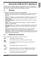
Features and benefits Bold monospace font 1.3 About the KVM s2-0411 Appliance This indicates user inputs in examples. Features and benefits On-screen management through the OSCAR® for Fujitsu-Siemens Computers graphical user interface provides easy system configuration and target device selection. Figure 1: KVM s2-0411 appliance 1.3.
About the KVM s2-0411 Appliance OSCAR graphical user interface The KVM-IAs enable direct KVM connectivity to target devices that are attached to the appliance. Each KVM s2-0411 appliance has four analog rack interface (ARI) ports for connecting KVM-IAs. The KVM-IAs that work with the KVM s2-0411 appliance support target devices with PS/2, Sun, and USB ports. When using the OSCAR interface in conjunction with KVM-IAs, you can easily switch between platforms. 1.3.
Flash upgradability 4 About the KVM s2-0411 Appliance 590-595-609A
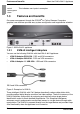
2 Installation 2.1 Required items Before you install the appliance, make sure that you have all the required items. The following items come with the KVM s2-0411 appliance: • Power cord • One null modem serial cable • Rack-mounting brackets and mounting hardware • Documentation CD • Quick Installation Guide • Warranty Card In addition to the items that come with the appliance, you must provide one KVM-IA (KVM or USB) and one Cat 5 patch cable for each attached target device or appliance.
Rack mounting the appliance • • • • • • • • • Installation Allow the appliance to cool before removing covers or touching internal components. Operate the appliance only from the type of external power source that is indicated on the electrical ratings label. If you are not sure of the type of power source that is required, consult the service provider or local power company.
Installation • Installing the appliance horizontally in the 1U rack mounting space Reliable earthing: Maintain reliable earthing of rack-mounted equipment. Pay particular attention to supply connections other than direct connections to the branch circuit (for example, use of power strips). 2.3.2 Installing the appliance horizontally in the 1U rack mounting space The filler panel must be placed in front of the rack when the appliance is mounted in the horizontal 1U orientation.
Installing the KVM s2-0411 appliance 2.4 Installation Installing the KVM s2-0411 appliance Connect the supplied power cord into the rear of the appliance and then into a power source. Figure 4 illustrates one possible configuration for the KVM s2-0411 appliance. See the following detailed set of procedures to install the appliance.
Installation 2.4.1 Connecting a KVM-IA to each target device Connecting a KVM-IA to each target device Attach the color-coded connectors of the KVM-IA to the keyboard, monitor, and mouse ports on the first target device that you connect to the appliance. Attach one end of the Cat 5 cable to the RJ-45 connector on the KVM-IA. Connect the other end of the Cat 5 cable to an ARI port on the rear of the KVM s2-0411 appliance. Repeat steps 1 to 4 for all target devices that you are attaching. 2.4.
Attaching an earlier appliance model to the KVM s2-0411 appliance Installation Local user KVM s2-0411 appliance KVM-IA KVM-IA Earlier appliance models Target device 1 Target device 2 Figure 5: Appliance configuration with earlier appliance models 2.5.1 10 Attaching an earlier appliance model to the KVM s2-0411 appliance Mount the earlier appliance model into the rack according to the instructions that are included with that device.
Installation Attaching an incompatible switch model Connect the other end of the Cat 5 cable to any available ARI port on the rear panel of the KVM s2-0411 appliance. Turn off and turn on the target devices to the tiered appliance according to the instructions that are included with that device. Turn off and turn on the tiered appliance to enable its local port to recognize the KVM-IA. Repeat the above steps for all tiered appliances that you want to attach to the switching system.
Setting up the KVM s2-0411 appliance 12 Installation 590-595-609A
3 Basic operations 3.1 Controlling the switching system from the analog user port The KVM s2-0411 appliance has PS/2 keyboard and mouse ports on the rear panel that you can use to connect a PS/2 keyboard and mouse for direct analog access. The appliance uses the OSCAR interface, which has menus to configure the switching system and select target devices. 3.
Starting the OSCAR interface Basic operations The Port column indicates the ARI port to which each target device is connected. If an earlier appliance model is connected to a KVM s2-0411 appliance, the ARI port number is shown first, followed by the number of the appliance port to which the target device is connected. For example, in Figure 3.1, the target device named Acton is connected to ARI port 06 and appliance port 01.
Basic operations 3.3 Connecting a user to a target device Connecting a user to a target device Use the Main window of the OSCAR interface to select a target device to which you want to connect. When you select a target device, the keyboard and mouse are automatically reconfigured to the correct settings for that target device.
Using the OSCAR interface Basic operations Key, key combination, or mouse action Result F1 Display help for the current window. Escape In the OSCAR main window: Close the OSCAR interface and return to the status flag on the desktop. In all other windows: Close the current window, without saving changes, and return to the previous window. In pop-up windows: Close the pop-up window and return to the current window.
Basic operations 3.5 Configuring the appliance and the OSCAR interface Configuring the appliance and the OSCAR interface To configure the appliance and the OSCAR interface, start the OSCAR interface and click Setup. The following illustration shows the Setup window. Figure 7: Setup window The following table describes the options in the Setup window. Option Purpose Menu Order the list of target devices by target device name, EID number, or port number.
Assigning target device names Basic operations Option Purpose Devices Specify the number of ports that are on the attached tiered appliance. Names Assign a unique name to each target device. Keyboard Specify the keyboard country code. Scan Set up a custom scan pattern for up to 100 target devices. Switch Specify the appliance mode. Network Specify the network speed and configuration, IP address, netmask, and gateway for the switching system.
Basic operations Assigning device types a configurable appliance from the list, the Modify button becomes available, so you can assign it the correct number of ports. 3.5.2.1 Accessing the Devices window Press Print Screen to start the OSCAR interface. The Main window opens. Click Setup - Devices. The Devices window opens. Figure 8: Devices window When the KVM s2-0411 appliance discovers a tiered appliance, the port numbering changes to accommodate each target device under that appliance.
Changing the display behavior Basic operations Figure 9: Device Modify window Select or type the number of ports that are supported by the tiered appliance and click OK. Repeat steps 1 to 3 for each port for which you want to assign a device type. Click OK in the Devices window to save settings. 3.5.3 Changing the display behavior Use the Menu window to change the order of target devices and set a screen delay for the OSCAR interface.
Basic operations Selecting display language Figure 10: Menu window 3.5.3.2 Selecting the order of the target devices Click one of the following buttons: • Select Name to list the target devices alphabetically by target device name. -or• Select EID to list the target devices numerically by EID number. -or• Select Port to list the target devices numerically by port number. Click OK. 3.5.3.
Controlling the status flag Basic operations Figure 11: Language window Press Print Screen to start the OSCAR interface. The Main window opens. Click Setup - Language. The Language window opens. In the Language window, select the language and click OK. 3.5.5 Controlling the status flag The status flag is displayed on the desktop and indicates the name or EID number of the selected target device or the status of the selected port.
Basic operations Setting the keyboard country code 3. Set one or more of the following settings: • Select Name or EID to specify the information that is displayed in the flag. -or• Select Displayed to display the flag all the time, or select Timed to display the flag for only 5 seconds after you select a target device. -or• In the Display Color section, select the flag color. -or• Select Opaque to make the flag solid, or select Transparent to make the desktop visible through the flag.
Setting the keyboard country code Basic operations Figure 12: Keyboard window 3.5.6.1 Changing the keyboard country code Press Print Screen to start the OSCAR interface. The Main window opens. Click Setup - Keyboard. The Keyboard window opens. Select the country code for the keyboard, and click OK. Confirm the change in the Keyboard Warning window. Click OK to save the change, or click X or press Escape to exit without saving the change. 3.5.6.
Basic operations Setting the keyboard country code 3.5.6.3 Enabling the screen saver Press Print Screen. The Main window opens. Click Setup - Security. If a password is set, the Password window opens. Type the password and click OK. Select the Enable Screen Saver check box. In the Inactivity Time field, type the number of seconds (1 through 99) that must elapse before the screen saver starts. If the monitor is Energy Star compliant, select Energy; otherwise, select Screen.
Managing target device tasks using the OSCAR interface 3.6 Basic operations Managing target device tasks using the OSCAR interface From the Commands window, you can manage the switching system and user connections, enable Scan mode, and update the firmware. Feature Purpose KVM-IA Status View the version and upgrade status of the KVM-IA. Display Config View current display settings. Run Diagnostics Configure and begin diagnostics on target devices. Scan Enable Begin scanning the target devices.
Basic operations Displaying version information Figure 13: Commands window 3.6.2 Displaying version information You can use the OSCAR interface to view the versions of the KVM s2-0411 appliance and the KVM-IA firmware. Press Print Screen. The Main window opens. Click Commands - Display Versions. The Version window opens. The top pane of the window lists the subsystem versions in the appliance.
Upgrading the firmware Basic operations Click the KVM-IA button to view individual KVM-IA version information. The KVMIA Select window opens. Select a KVM-IA to view and click the Version button. The KVM-IA Version window opens. Click X to close the CO Version window. 3.6.3 Upgrading the firmware You can also use the OSCAR interface to upgrade the firmware available for the KVM s2-0411 appliance. For optimum performance, keep the firmware current. Figure 15: Upgrade window Press Print Screen.
Basic operations 3.8 Viewing and disconnecting user connections Viewing and disconnecting user connections You can view and disconnect users from target devices through the User Status window. The user (U) is always visible; however, you can display either the target device name or EID number to which a user is connected. If no user is currently connected, both the User and Server Name fields are blank. Figure 16: User Status window 3.8.0.
Scanning the switching system Basic operations appliance. With communication re-established between the target device and the appliance, functionality is restored to the user. This function is for Microsoft Windows-based computers only. Resetting the keyboard and mouse on a target device running any other operating system might require that you reboot that target device. Press Print Screen. The Main window opens. Click Commands - Display Versions - KVM-IA.
Basic operations The window contains a listing of all target devices that are attached to the appliance. To select target devices to be scanned, complete one of the following steps: • Select the check box next to the target devices that you want to scan. -or• Double-click on a target device name or port. -or• Press Alt and the EID number of the target device that you want to scan. You can select up to 16 target devices from the list.
Canceling scan mode Basic operations Figure 18: Commands window Select Scan Enable in the Commands window. Scanning will be begin immediately. Click X to close the Commands window. 3.9.4 Canceling scan mode Complete one of the sollowing steps: If the OSCAR interface is open, select a target device. -or If the OSCAR interface is not open, move the mouse or press any key on the keyboard to stop scanning at the currently selected target device. 3.
Basic operations Running switching system diagnostics Figure 19: Diagnostics window Next to each item that will be tested, you will see a pass (green circle) or fail (red x) symbol to the left of each item as that test finishes. The following table details each of the tests. Test Description Firmware CRCs Reports on the condition of the main board RAM. LAN Connection Reports on the condition of the LAN connection. On-line KVMIAs Indicates the total number of currently connected and turned on KVM-IAs.
Running diagnostic tests 3.10.1 Basic operations Running diagnostic tests Click Commands - Run Diagnostics. A warning message indicates that all users will be disconnected. Click OK to begin diagnostics. All users are disconnected and the Diagnostics window opens. As each test is finished, a pass (green circle) or fail (red x) symbol is visible. The test is complete when the last test symbol is visible.
4 Computer terminal operations 4.1 The Console menu Each appliance can be configured at the appliance level through the Console menu interface accessed through the configuration port on the rear of the appliance. All terminal commands are accessed through a terminal or computer running terminal emulation software. 4.1.1 Configuring the network using the Console menu When you turn on the appliance, the appliance initializes for approximately one minute.
Other Console Main menu options Computer terminal operations When DHCP is selected, the IP Address, Netmask, and Default Gateway settings are automatically assigned to the appliance and cannot be modified by a user. If you are using the DHCP option, configure the DHCP target device to provide an IP address to the appliance and then skip step 5.
5 Appendices 5.1 Flash upgrades 5.1.1 Upgrading the KVM s2-0411 appliance Use the KVM s2-0411 appliance Flash upgrade feature to update the appliance with the latest firmware available. Items needed for the upgrade • • • • Target device that is running a terminal program Available serial port (COM port) on the target device Serial cable that connects the appliance and the target device Firmware update 5.1.2 Upgrading a new Flash file Go to http://www.fujitsu-siemens.
Upgrading the KVM-IA firmware Appendices Figure 21: KVM-IA Status window Click one or more types of modules to upgrade. Click Upgrade. The KVM-IA Upgrade window opens. Click OK to initiate the upgrade and return to the KVM-IA Status window. 5.1.3.2 Upgrading KVM-IA firmware individually Press Print Screen. The Main window opens. Click Commands > Display Versions. The KVM-IA Version window opens.
Appendices Upgrading the KVM-IA firmware Click KVM-IA to view individual KVM-IA version information. The KVM-IA Select window opens. Figure 23: KVM-IA Select window Select a KVM-IA to upgrade and click the Version button. The KVM-IA Version window opens. Click the Load Firmware button. The KVM-IA Load window opens. Click OK to initiate the upgrade and return to the Status window. During an upgrade, the KVM-IA status indicator in the Main window is yellow.
Repairing damaged firmware 5.1.4 Appendices Repairing damaged firmware In the rare case that the firmware is damaged after a firmware upgrade (which might happen if the appliance is turned off and turned on during the upgrade process), the appliance will remain in boot mode. In this mode, the Power LED at the rear panel flashes at about 1Hz, and the appliance attempts to restore the firmware over TFTP using the following default configuration: • TFTP client IP address 10.0.0.
Appendices UTP cabling 5.2 UTP cabling The following information is intended to brief you on various aspects of connection media. The performance of a switching system depends on high quality connections. Poor quality or poorly installed or maintained cabling can diminish system performance.This appendix is for information purposes only. Consult with the local code officials or cabling consultants prior to any installation. 5.2.
Cabling installation, maintenance, and safety tips 5.2.3 Appendices Cabling installation, maintenance, and safety tips The following is a list of important safety considerations that should be reviewed prior to installing or maintaining the cables: • It is best to keep all Cat 5 runs to a maximum of 10 meters each; however, some cables may run longer. • Maintain the twists of the pairs all the way to the point of termination, or no more that one-half inch untwisted.
Appendices 5.
Technical specifications Dimensions (H x W x D) 4.37 cm x 43.18 cm x 20.32 cm; 1U form factor (1.72 in. x 17.00 in. x 8.00 in.) Weight 2.6 kg (5.75 lb) without cables Appendices Power Supply Heat dissipation 92 BTU/Hr Airflow 8 CFM Power consumption 12.5 Watts AC-input power 40 Watt maximum AC-input voltage rating 100 to 240 V ac Autosensing AC-input current rating 0.
Appendices 5.4 Technical Support Technical Support Our Technical Support staff is ready to assist you with any installation or operating issues you encounter with your Fujitsu Siemens product. If an issue should develop, follow the steps below for the fastest possible service: Check the pertinent section of this manual to see if the issue can be resolved by following the procedures outlined. Check our web site at http://www.fujitsu-siemens.com/support and click on Services & Support.
Before you call 46 Appendices 590-595-609A
KVM s2-0411 Bedienungsanleitung Auflage Januar 2006
Kommentare… Vorschläge… Verbesserungen Unsere Abteilung für technische Dokumentation würde gerne Ihre Meinung zu diesem Handbuch erfahren. Ihr Feedback hilft uns, unsere Dokumentation zu optimieren, indem Ihre individuellen Anforderungen erfüllt werden. Sie finden hinten im Handbuch FaxFormulare, mit denen Sie uns Ihre Kommentare zuschicken können. Dort befindet sich auch die Adresse der entsprechenden Abteilung für technische Dokumentation.
Inhalt 1 1.1 1.2 1.3 1.3.1 1.3.2 1.3.3 1.3.4 1.3.5 1.3.6 2 2.1 2.2 2.2.1 2.3 2.3.1 2.3.2 2.4 2.4.1 2.4.2 2.5 2.5.1 2.5.2 2.6 3 3.1 3.2 3.3 3.4 3.5 3.5.1 3.5.1.1 3.5.1.2 3.5.2 3.5.2.1 3.5.2.2 3.5.3 3.5.3.1 590-595-609A Die KVM s2-0411-Einheit......................................................................... 1 Glossar ...................................................................................................... 1 Darstellungskonventionen ........................................................
Inhalt 3.5.3.2 3.5.3.3 3.5.3.4 3.5.4 3.5.5 3.5.5.1 3.5.6 3.5.6.1 3.5.6.2 3.5.6.3 3.5.6.4 3.5.6.5 3.5.6.6 3.6 3.6.1 3.6.2 3.6.3 3.7 3.8 3.8.0.1 3.8.0.2 3.8.0.3 3.9 3.9.1 3.9.2 3.9.3 3.9.4 3.10 3.10.1 4 4.1 4.1.1 4.1.2 4.1.2.1 4.1.2.2 4.1.2.3 4.1.2.4 4.1.2.5 4.1.2.6 Auswählen der Anzeigereihenfolge für Zielgeräte................................... 22 Auswählen einer Tastenkombination zum Starten der OSCAR-Benutzeroberfläche ...................................................................
Inhalt 5 5.1 5.1.1 5.1.2 5.1.3 5.1.3.1 5.1.3.2 5.1.4 5.1.4.1 5.2 5.2.1 5.2.2 5.2.3 5.3 5.4 5.4.1 590-595-609A Anhänge ................................................................................................. 39 Flash-Aktualisierung ................................................................................ 39 Aktualisieren der KVM s2-0411-Einheit................................................... 39 Aktualisieren einer neuen Flash-Datei.....................................................
Inhalt 590-595-609A
1 Die KVM s2-0411-Einheit Die KVM s2-0411®-Einheit kombiniert analoge KVM-Switching-Technologie mit ausgereiftem Kabelmanagement. Sie ermöglicht den Zugriff für zwei Benutzer gleichzeitig und verfügt über eine intuitive Benutzeroberfläche. Die KVM s2-0411-Einheit verfügt über PS/2. 1.1 Glossar In diesem Handbuch werden die folgende Begriffe verwendet: • ACI-Port: ACI steht für „Analog Console Interface“.
Merkmale und Vorteile Die KVM s2-0411-Einheit Verweist auf einen Schritt, den Sie ausführen müssen. - und • Diese Zeichen weisen auf Gliederungen hin. Bold monospace font Gibt Eingaben des Benutzers in Beispielen an. 1.3 Merkmale und Vorteile On-Screen-Verwaltung über die grafische Benutzeroberfläche OSCAR® von FujistuSiemens Computers, die eine einfache Systemkonfiguration und Auswahl der Zielgeräte ermöglicht. Abbildung 1: KVM s2-0411-Einheit 1.3.
Die KVM s2-0411-Einheit Grafische Benutzeroberfläche OSCAR Diese intelligenten KVM-IAs im CAT 5-Design reduzieren den Kabelaufwand entscheidend und bieten gleichzeitig optimale digitale Bildschirmauflösungen und Videoeinstellungen. Der integrierte Speicher des KVM-IA vereinfacht die Konfiguration, indem jedem angeschlossenen Zielgerät eindeutige Identifikationscodes zugewiesen und dauerhaft gespeichert werden.
Flash-Aktualisierungen 4 Die KVM s2-0411-Einheit 590-595-609A
2 Installation 2.1 Erforderliche Komponenten Stellen Sie vor der Installation der Einheit sicher, dass alle erforderlichen Komponenten vorhanden sind.
Allgemeine Sicherheitshinweise • • • • • • • • • • • 6 Installation Achten Sie darauf, die Komponenten der Einheit nicht mit Nahrungsmitteln oder Flüssigkeiten zu verunreinigen und betreiben Sie die Einheit nicht in feuchter Umgebung. Wenn die Einheit Feuchtigkeit ausgesetzt wurde, sehen Sie im entsprechenden Abschnitt der Anleitung zur Störungsbeseitigung nach oder nehmen Sie Kontakt mit einem geschulten Wartungstechniker auf. Verwenden Sie die Einheit nur mit zugelassenen Geräten.
Installation 2.3 Rackbefestigung der Einheit Rackbefestigung der Einheit Vor der Installation der Einheit und anderer Komponenten im Rack (falls noch nicht installiert) muss das Rack am vorgesehenen Standort stabilisiert werden. Bestücken Sie das Rack von unten nach oben mit Komponenten. Vermeiden Sie eine ungleichmäßige Belastung und achten Sie darauf, dass das Rack nicht überladen wird. 2.3.
Horizontale Installation der Einheit in den 1 HE-Rackplatz Installation Abbildung 3: Horizontale Installation der Einheit 8 590-595-609A
Installation 2.4 Installieren der KVM s2-0411-Einheit Installieren der KVM s2-0411-Einheit Schließen Sie das mitgelieferte Stromkabel hinten an die Einheit und dann an eine Stromquelle an. Abbildung 4 zeigt eine mögliche Konfiguration der KVM s2-0411-Einheit. Das folgende Verfahren hilft Ihnen, die Einheit zu installieren.
Anschließen eines KVM-IA an jedes Zielgerät 2.4.1 Installation Anschließen eines KVM-IA an jedes Zielgerät Schließen Sie die farbkodierten Stecker des KVM-IA an die Tastatur-, Bildschirmund Mausports am ersten Zielgerät an, das an die Einheit angeschlossen werden soll. Schließen Sie ein Ende des CAT 5-Kabels an den RJ45-Anschluss des KVM-IA an. Schließen Sie das andere Ende des CAT 5-Kabels an einen ARI-Port auf der Rückseite der KVM s2-0411-Einheit an.
Installation Anschließen eines älteren Einheitenmodells an die KVM s2-0411-Einheit Lokaler Benutzer KVM s2-0411-Einheit KVM-IA KVM-IA Ältere Einheitenmodelle Zielgerät 1 Zielgerät 2 Abbildung 5: Einheiten-Konfiguration mit älteren Einheitenmodellen 2.5.1 11 Anschließen eines älteren Einheitenmodells an die KVM s2-0411-Einheit Befestigen Sie die ältere Einheit im Rack und beachten Sie dabei die geltenden Anweisungen.
Anschließen eines nicht kompatiblen Switch-Modells Installation Schließen Sie das andere Ende des CAT 5-Kabels an einen beliebigen verfügbaren ARI-Port auf der Rückseite der KVM s2-0411-Einheit an. Schalten Sie die mit der gestuften Einheit verbundenen Zielgeräte aus und wieder ein und beachten Sie dabei die geltenden Anweisungen. Schalten Sie die gestufte Einheit aus und wieder ein, damit der lokale Port den KVM-IA erkennt.
3 Normalbetrieb 3.1 Steuern des Switching-Systems über den Analogport Die KVM s2-0411-Einheit verfügt an der Rückseite über Ports, an die Sie eine USBoder PS/2-Tastatur und -Maus zum direkten analogen Zugriff anschließen können. Die Einheit verwendet die grafische Benutzeroberfläche OSCAR, die über Menüs zur Konfiguration Ihres Systems und zur Auswahl der Zielgeräte verfügt. 3.
Aufrufen der OSCAR-Benutzeroberfläche Normalbetrieb Das Hauptmenü listet die Zielgeräte im Switching-System auf. Sie können die Liste der Zielgeräte nach Namen, EID- oder Port-Nummern sortieren, indem Sie auf die entsprechende Schaltfläche Name, EID oder Port klicken. Die Spalte Port zeigt den ARI-Port, an den das jeweilige Zielgerät angeschlossen ist.
Normalbetrieb 3.3 Verbinden eines Benutzers mit einem Zielgerät Verbinden eines Benutzers mit einem Zielgerät Wählen Sie im Hauptmenü der OSCAR-Benutzeroberfläche ein Zielgerät aus, mit dem Sie eine Verbindung herstellen möchten. Wenn Sie ein Zielgerät auswählen, werden Tastatur und Maus automatisch auf die richtigen Einstellungen für das Zielgerät konfiguriert.
Verwenden der OSCAR-Benutzeroberfläche Normalbetrieb Taste, Tastenkombination Wirkung oder Mausaktion Druck, Druck Der Tastenanschlag Druck wird an das aktuell ausgewählte Zielgerät gesendet. Das heißt, der Bildschirminhalt des Zielgeräts wird erfasst. Wenn die Taste Druck über Setup - Menü nicht als Tastenfolge zum Aufrufen von OSCAR ausgewählt wurde, müssen Sie die Taste Druck nur einmal betätigen, um den Bildschirminhalt des Zielgeräts zu erfassen. F1 Hilfe zum aktuellen Bildschirm wird angezeigt.
Normalbetrieb Konfiguration der Einheit und der OSCAR-Benutzeroberfläche Taste, Tastenkombination Wirkung oder Mausaktion Druck, Alt+0 Die Verbindung des Benutzers mit dem ausgewählten Zielgerät wird getrennt. Beachten Sie, dass die Null auf der Haupttastatur eingegeben werden muss, nicht auf der Zehnertastatur. Druck, Pause Der Bildschirmschoner wird umgehend gestartet und der Benutzer gesperrt, wenn der Bildschirmschoner kennwortgeschützt ist.
Konfiguration der Einheit und der OSCAR-Benutzeroberfläche Normalbetrieb Abbildung 7: Dialogfeld „Setup“ Die folgende Tabelle beschreibt die Optionen im Dialogfeld „Setup“. Option Zweck Menü Sortiert die Liste der Zielgeräte nach Name, EID-Nummer oder Portnummer des Zielgeräts. Einstellen einer Zeitverzögerung, um festzulegen, wie viel Zeit zwischen dem Betätigen der Taste „Druck“ und dem Öffnen der OSCAR-Benutzeroberfläche vergeht.
Normalbetrieb Zuweisen von Zielgerätenamen Option Zweck Scannen Einrichten eines benutzerdefinierten Scan-Schemas für bis zu 100 Zielgeräte. Switch Den Modus der Einheit einstellen. Netzwerk Einstellen von Netzwerkgeschwindigkeit und -konfiguration, IP-Adresse, Netzmaske und Gateway für das Switching-System. Tabelle 3: Setup-Funktionen zur Verwaltung von Routineaufgaben für die Zielgeräte 3.5.
Gerätetypen zuordnen 3.5.2 Normalbetrieb Gerätetypen zuordnen Die KVM s2-0411-Einheit erkennt gestufte Remote Console Switches automatisch. Sie müssen jedoch die Portanzahl der gestuften Einheit im Dialogfeld „Geräte“ einstellen. Fujitsu Siemens AutoView Console Switches und andere ältere Remote Console SwitchModelle werden in der Kategorie „Typ“ für die gestufte Einheit angezeigt. Die Schaltfläche Ändern wird aktiviert, wenn Sie eine konfigurierbare Einheit in der Liste auswählen.
Normalbetrieb Ändern des Anzeigeverhaltens Abbildung 9: Dialogfeld „Geräte ändern“ Wählen Sie die Anzahl an Ports aus, die von der gestuften Einheit unterstützt werden oder geben Sie die Anzahl über die Tastatur ein. Klicken Sie auf OK. Die Schritte 1-3 für jeden Port ausführen, der einem Gerätetyp zugewiesen werden soll. Klicken Sie im Dialogfeld „Geräte“ auf OK, um die Einstellungen zu speichern. 3.5.
Ändern des Anzeigeverhaltens Normalbetrieb Abbildung 10: „Menü“, Dialogfeld 3.5.3.2 Auswählen der Anzeigereihenfolge für Zielgeräte Klicken Sie auf eine der folgenden Schaltflächen: • Klicken Sie auf Name, um die Zielgeräte alphabetisch nach Namen zu sortieren. - oder • Klicken Sie auf EID, um die Zielgeräte numerisch nach EID-Nummern zu sortieren. - oder • Klicken Sie auf Port, um die Zielgeräte numerisch nach Portnummern zu sortieren. Klicken Sie auf OK. 3.5.3.
Normalbetrieb 3.5.4 Auswählen der Sprache Auswählen der Sprache Im Dialogfeld „Sprache“ können Sie die Sprache ändern, in der die OSCAR-Benutzeroberfläche angezeigt wird. Abbildung 11: Dialogfeld „Sprache“ Betätigen Sie die Taste Druck, um die OSCAR-Benutzeroberfläche aufzurufen. Das Hauptmenü wird geöffnet. Klicken Sie auf Setup - Sprache. Das Dialogfeld „Sprache“ wird geöffnet. Wählen Sie im Dialogfeld „Sprache“ die gewünschte Sprache aus und klicken Sie auf OK. 3.5.
Einstellen der länderspezifischen Tastatureinstellungen Normalbetrieb 3.5.5.1 Festlegen der Status-Flag-Einstellungen 1. Betätigen Sie die Taste Druck. Das Hauptmenü wird geöffnet. 2. Klicken Sie auf Setup - Flag. 3. Legen Sie eine oder mehrere der folgenden Einstellungen fest: • Wählen Sie Name oder EID aus, um die im Flag angezeigten Informationen festzulegen.
Normalbetrieb Einstellen der länderspezifischen Tastatureinstellungen Abbildung 12: Dialogfeld „Tastatur“ 3.5.6.1 Ändern der länderspezifischen Tastatureinstellungen Betätigen Sie die Taste Druck, um die OSCAR-Benutzeroberfläche aufzurufen. Das Hauptmenü wird geöffnet. Klicken Sie auf Setup - Tastatur. Das Dialogfeld „Tastatur“ wird geöffnet. Wählen Sie die länderspezifische Tastatureinstellung aus und klicken Sie auf OK. Bestätigen Sie die Änderung im Dialogfeld „Tastaturwarnung“.
Einstellen der länderspezifischen Tastatureinstellungen Normalbetrieb 3.5.6.3 Aktivieren des Bildschirmschoners Betätigen Sie die Taste Druck. Das Hauptmenü wird geöffnet. Klicken Sie auf Setup - Sicherheit. Wenn ein Kennwort eingerichtet wurde, wird das Dialogfeld „Kennwort“ angezeigt. Geben Sie Ihr Kennwort ein und klicken Sie auf OK. Aktivieren Sie das Kontrollkästchen Bildschirmschoner.
Verwalten der Aufgaben der Zielgeräte über die OSCAR-Benutzeroberfläche 3.6 Normalbetrieb Verwalten der Aufgaben der Zielgeräte über die OSCAR-Benutzeroberfläche Im Dialogfeld „Befehle“ können Sie das Switching-System und die Benutzerverbindungen verwalten, den Scan-Modus aktivieren und die Firmware aktualisieren. Funktion Zweck KVM-IA-Status Zeigt Version und Aktualisierungsstatus des KVM-IA. Konfiguration anzeigen Zeigt die aktuellen Anzeigeeinstellungen.
Anzeigen der Versionsinformationen Normalbetrieb Abbildung 13: Dialogfeld „Befehle“ 3.6.2 Anzeigen der Versionsinformationen Mit der OSCAR-Benutzeroberfläche können Sie die Firmwareversionen für die KVM s2-0411-Einheit und den KVM-IA anzeigen. Betätigen Sie die Taste Druck. Das Hauptmenü wird geöffnet. Klicken Sie auf Befehle - Versionen anzeigen. Das Fenster „Version“ wird geöffnet. Die Subsystemversionen der Einheit werden in der oberen Hälfte des Fensters aufgeführt.
Normalbetrieb Aktualisieren der Firmware Klicken Sie auf die Schaltfläche KVM-IA, um Versionsinformationen zu individuellen KVM-IAs anzuzeigen. Das Dialogfeld „KVM-IA-Auswahl“ wird angezeigt. Wählen Sie einen KVM-IA zur Anzeige aus und klicken Sie auf die Schaltfläche Version. Das Dialogfeld für „KVM-IA-Version“ wird angezeigt. Klicken Sie auf X, um das Fenster „KVM-IA-Versionen“ zu schließen. 3.6.
Anzeigen und Trennen von Benutzerverbindungen 3.8 Normalbetrieb Anzeigen und Trennen von Benutzerverbindungen Im Dialogfeld „Benutzerstatus“ können Sie Benutzer anzeigen und ihre Verbindung mit Zielgeräten trennen. Der Benutzername (U) wird immer angezeigt. Es ist jedoch möglich, entweder den Namen oder die EID-Nummer des Zielgeräts, mit dem der Benutzer verbunden ist, anzuzeigen. Wenn gerade kein Benutzer mit einem Kanal verbunden ist, bleiben die Felder Benutzer und Servername leer.
Normalbetrieb Scannen des Switching-Systems 3.8.0.3 Zurücksetzen von Tastatur und Maus Wählen Sie Befehle - Geräte-Reset, um Tastatur und Maus zurückzusetzen. Wenn Tastatur oder Maus immer noch nicht reagieren, können Sie diese Peripheriegeräte u. U. durch einen Befehl zum Reset der Maus- und Tastatureinstellungen am Zielgerät wieder in Betrieb nehmen. Der Reset-Befehl überträgt eine Hot Plug-Sequenz an das Zielgerät, wodurch die Maus- und Tastatureinstellungen an die Einheit übertragen werden.
Entfernen eines Zielgeräts aus der Scan-Liste Normalbetrieb . Abbildung 17: Dialogfeld „Scannen“ Das Dialogfeld enthält eine Auflistung aller mit der Einheit verbundenen Zielgeräte. Führen Sie einen der folgenden Schritte durch, um Zielgeräte zum Scannen auszuwählen: • Aktivieren Sie das Kontrollkästchen neben den Zielgeräten, die gescannt werden sollen. - oder • Doppelklicken Sie auf den Namen oder Port eines Zielgeräts.
Normalbetrieb Starten des Scan-Modus • Klicken Sie auf die Schaltfläche Löschen, um alle Zielgeräte aus der ScanListe zu entfernen. Klicken Sie auf OK. 3.9.3 Starten des Scan-Modus Klicken Sie auf Befehle. Das Dialogfeld „Befehle“ wird geöffnet. Abbildung 18: Dialogfeld „Befehle“ Aktivieren Sie im Dialogfeld „Befehle“ das Kontrollkästchen Scan aktiviert. Der Scan-Vorgang startet sofort. Klicken Sie auf X, um das Fenster „Befehle“ zu schließen. 3.9.
Diagnosetests am Switching-System durchführen 3.10 Normalbetrieb Diagnosetests am Switching-System durchführen Die Integrität Ihres Switching-Systems kann mit dem Befehl „Diagnosetests“ überprüft werden. Durch diesen Befehl werden die auf dem Main Board befindlichen Subsysteme (Speicher, Kommunikation, Einheiten-Steuerung und Videokanäle) für jeden System Controller geprüft.
Normalbetrieb Starten der Diagnosestests Online KVM-IAs Zeigt die Gesamtanzahl der aktuell angeschlossenen und eingeschalteten KVM-IAs. Offline KVM-IAs Zeigt die Anzahl der KVM-IAs, die bislang erfolgreich angeschlossen wurden, aber ausgeschaltet sind. Suspekte KVM-IAs Zeigt die Anzahl der KVM-IAs, die erkannt wurden, jedoch entweder für eine Verbindung nicht verfügbar sind oder während des Ping-Tests nicht alle Pakete übertragen haben. Tabelle 6: Einzelheiten der Diagnosetests 3.10.
Starten der Diagnosestests 36 Normalbetrieb 590-595-609A
4 Terminalbetrieb des Computers 4.1 Konsolenmenü Jede Einheit kann auf Einheitenebene durch das Konsolenmenü konfiguriert werden, indem der Konfigurationsport an der Geräterückseite verwendet wird. Der Zugriff auf alle Terminalbefehle ist über ein Terminal oder einen Computer, auf dem eine TerminalEmulationssoftware ausgeführt wird, möglich. 4.1.1 Konfigurieren des Netzwerks über das Konsolenmenü Wenn Sie die Einheit einschalten, führt diese ca. 1 Minute lang eine Initialisierung durch.
Weitere Optionen im Konsolenhauptmenü Terminalbetrieb des Computers Statische IP-Adressen können für die Bereitstellung von benutzerdefinierten IPAdressen, Netzmasken und Standard-Gateways für die Einheit verwendet werden. Zur einfacheren Konfiguration empfiehlt es sich, eine statische IP-Adresse zu verwenden. DHCP ist ein Protokoll, das die Konfiguration von TCP/IP-fähigen Computern automatisiert.
5 Anhänge 5.1 Flash-Aktualisierung 5.1.1 Aktualisieren der KVM s2-0411-Einheit Über die Funktion Flash-Aktualisierung kann die KVM s2-0411-Einheit mit der neuesten Firmware aktualisiert werden. Für die Aktualisierung benötigen Sie Folgendes • • • • Ein Zielgerät, auf dem eine Terminalsoftware betrieben wird Einen verfügbaren seriellen Port (COM-Port) am Zielgerät Ein serielles Kabel, welches das Zielgerät mit der Einheit verbindet. Firmware-Update 5.1.
Aktualisierung der KVM-IA-Firmware 5.1.3 Anhänge Aktualisierung der KVM-IA-Firmware Die KVM-IAs können einzeln oder gleichzeitig aktualisiert werden. 5.1.3.1 Gleichzeitiges Aktualisieren mehrerer KVM-IAs Betätigen Sie die Taste Druck. Das Hauptmenü wird geöffnet. Klicken Sie auf Befehle > KVM-IA-Status. Das Dialogfeld für den KVM-IA-Status wird angezeigt. Abbildung 21: Dialogfeld „KVM-IA-Status“ Auf einen oder mehrere Modultypen klicken, die aktualisiert werden sollen. Klicken Sie auf Aktual..
Anhänge Aktualisierung der KVM-IA-Firmware Abbildung 22: Dialogfeld „KVM-IA-Version“ Klicken Sie auf KVM-IA, um Versionsinformationen zu individuellen KVM-IAs anzuzeigen. Das Dialogfeld „KVM-IA-Auswahl“ wird angezeigt. Abbildung 23: Dialogfeld „KVM-IA-Auswahl“ Wählen Sie einen KVM-IA zur Aktualisierung aus, und klicken Sie auf die Schaltfläche Version. Das Dialogfeld „ KVM-IA-Version“ wird angezeigt. Klicken Sie auf die Schaltfläche Firmware laden. Das Dialogfeld „KVM-IA laden” wird angezeigt.
Reparieren von beschädigter Firmware Anhänge Klicken Sie auf OK, um die Aktualisierung zu starten und zum Status-Fenster zurückzukehren. Während einer Aktualisierung ist die Statusanzeige des KVM-IA im Hauptmenü gelb. Der KVM-IA ist während einer Aktualisierung nicht verfügbar. Alle momentan aktiven Verbindungen zum Zielgerät über den KVM-IA werden getrennt, wenn eine Aktualisierung gestartet wird. 5.1.
Anhänge UTP-Kabel 5.2 UTP-Kabel Die folgenden Informationen bieten eine kurze Einführung in die verschiedenen Aspekte der Verbindungsmedien ein. Die Leistungsfähigkeit Ihres Switching-Systems hängt von der Qualität der Anschlüsse ab. Schlechte Kabelqualität oder unzureichend verlegte oder gewartete Kabel können die Systemleistung beeinträchtigen. Dieser Anhang dient nur zu Informationszwecken. Sprechen Sie vor der Installation mit einem qualifizierten Elektriker oder Verkabelungstechniker vor Ort. 5.2.
Kabelinstallation, Kabelwartung und Sicherheitshinweise 5.2.3 Anhänge Kabelinstallation, Kabelwartung und Sicherheitshinweise Im Folgenden werden wichtige Sicherheitshinweise aufgelistet, die bei der Installation und Wartung von Kabeln beachtet werden sollten: • Alle CAT 5 Kabel sollten jeweils nur über eine maximale Länge von 10 Metern verlegt werden. Manche Kabel können auch auf einer größeren Länge verlegt werden.
Anhänge 5.3 Technische Daten Technische Daten Ports der Zielserver Anzahl 4 Kabeltypen KVM-IA PS/2, KVM-IA USB und KVM-IA Sun Anschlüsse RJ-45 Sync-Arten Unabhängig horizontal und vertikal Plug & Play DDC2B Bildschirmauflösung 640 x 480 bei 60 Hz (min. für lokalen Port und Remote-Port) 800 x 600 bei 75 Hz 960 x 700 bei 75 Hz 1024 x 768 bei 75 Hz 1280 x 1024 bei 75 Hz (max.
Technische Daten Anhänge Abmessungen Abmessungen (H x B x T) 4,37 x 43,18 x 20,32 cm; Formfaktor 1 HE Gewicht 2,6 kg ohne Kabel Stromversorgung Wärmeabstrahlung 97.000 Joule/Std. (92 BTU/Std.
Anhänge 5.4 Technischer Kundendienst Technischer Kundendienst Unser technischer Kundendienst steht Ihnen jederzeit für Fragen hinsichtlich Installation und Betrieb Ihres Produkts von Fujitsu Siemens zur Verfügung. Verfahren Sie zur schnellstmöglichen Problemlösung wie folgt: Sehen Sie im entsprechenden Abschnitt der Bedienungsanleitung nach, ob das Problem mit den vorgeschlagenen Abhilfemaßnahmen gelöst werden kann. Besuchen Sie unsere Webseite unter http://www.fujitsu-siemens.
Vor dem Anruf 48 Anhänge 590-595-609A
User Guide / Bedienungsanleitung control KVM series2-0411 Keyboard/Video/Mouse Switch 590-595-609A English / Deutsch 2