
User Manual


Siemens Building Technologies CA2N1612E / 11.1998
Landis & Staefa Division 3/4
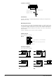
Connection diagrams - staefa integral RS
Terminal layout
1) Standard, 5-wire
INTEGRAL RSM (see Note 1) INTEGRAL RSA (see Note 2)
1
2
3
4
5
6
7
8
92.00289
Logik
KRT-1L
1
2
3
4
5
6
7
8
92.00291
Logic
1
2
3
4
1
2
3
4
KRT-1L
NKDG
NKDG
1
2
3
4
5
6
7
8
92.00292
Logik
K4
K1
K2
KRT-1L
NRK16(-B)
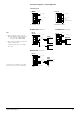
INTEGRAL RSC (see Note 2)
1
2
3
4
5
6
7
8
92.00293
Logik
+
–
+
KRT-1L
NRUE
NRUF
A separate order is required for the SAPIM
macro used to process the switch functions.
Note
1) Only one KRT-1B or 1 KRT-1L may be
fitted per NTOM(S) output module carrier
i.e. max. 1 KRT-1B for NRUA, NRUB
max. 2 KRT-1B for NRUC, NRUD
2) Only one KRT-1B or KRT-1L may be fitted
per RSA or RSC module
For KRT-1L specification, see catalogue
sheet 1613.
1)
KRT-1B
KRT-1B
KRT-1B
1
2
3
4
5
6
7
8
92.00290
Logik
KRT-1L
KRT-1B
T1 output
T1 output
T1 output T1 output
T1 output
+5 ... 15 VDC
GND
Out
+5 ... 15 VDC
GND
wRa and
mode selector switch
GND
+10 VDC
0 ... 10 VDC
A1 ... J1
A2 ... J2
+10 VDC
GND
0 ... 10 VDC
(analogue output)
(analogue intput)
Interchangeable wires
(supply from
NTOMS)
(NTIM)
2) KRT-1B
2) Alternative, 4-wire