
User Manual


CA2N1612E / 11.1998 Siemens Building Technologies
2/4 Landis & Staefa Division
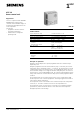
T1 sensor correction
Construction
The unit is supplied in a standard multi-part plastic housing. (For description and
dimensions see 1718)
T1
Factory setting (Midpoint) ± 0 K
Negative correction –
Positive correction +
9H547
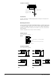
Connection diagram
(max. 2 KRT-1B per controller)
1 7 9 8 A F
9H804
RH500
GND +5V wRA T1
1 2 5 7KRT-1B 6
1 2 5 76KRT-1B
1 7 9 8 ARH500 A
GND +5V wRA T1
1 2 5 7KRT-1B 6
1 2FR-T1
F
1 KRT-1B action on both heating circuits
Interchangeable wires
Terminal layout
(max. 2 KRT-1B per controller)
KRT-1B
+ 5 V/5 mA (RH500), +10 V/10 mA (NRK16)
Room setpoint and operating mode switch
1
2
3
4
5
6
7
8
9H746
Logik
Mounting instructions
The room control unit should be mounted approximately 1.5 m above floor level. If
the temperature sensor is used, locations where it will be exposed to undue influen-
ces from heat, draughts and moisture (e.g. next to doors, windows and fireplaces)
should be avoided; locations with poor air circulation (e.g. corners, niches) should
also be avoided.
A frame is supplied as an accessory for surface mounting.
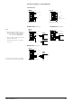
13 6 21 20 12 7
9H805 A
RH500/G
GND +5V wRA T1
1 2 5 7KRT-1B 6
1 2 5 76KRT-1B
13 6 21 20 12RH500/G
GND +5V wRA T1
1 2 5 7KRT-1B 6
1 2FR-T1
7
1 2 5 7KRT-1B 6
...1...2 K4 K2NRK16 K1
A...J +10V wRAGND
Interchangeable wires
GND
1 KRT-1B action on both heating circuits
Interchangeable wires