
User`s manual


CHAPTER 2: PROGRAMMING
11
Each 16-bit location may contain two ASCII characters (1 byte each).
By default, the most significant byte of the base address stores the first
character, the least significant byte stores the second character, the first
byte of the next sequential location stores the third character, and so on.
The data held in this range of address locations is expected to be an
ASCII data format.
Note: The ASCII data format is very useful for PLC applications reading
ASCII data from bar code readers or data collection terminals.
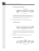
Timer (KT)
Time-
base
Range = 000.0 to 999.d
Value
Bit
15
Bit
12
Bit
11
Bit
0
Bit
9
16-Bit Timer
LSB
MSB
Bit
13
Bit
10
This data type displays the first 10 bits of a 16-bit register location as a
3-digit (decimal) unsigned integer. The range for the Timer selection is
000.0 to +999.d, where d is the timebase (0 = 0.01 sec/count, 1 = 0.1
sec/count, 2 = 1.0 sec/count , and 3 = 10 sec/count). Timebase d is
found in Bits 12 and 13.
Note: This data format may not be scaled to different engineering units.
Counter (KC)
Range = 0 to 999
Value
Bit
15
Bit
0
Bit
9
16-Bit Counter
LSB
MSB
Bit
10
This data type displays the first 10 bits of a 16-bit register location as a
3-digit (decimal) unsigned integer. The range for the Counter selection
is 0 to +999.
Note: This data format may not be scaled to different engineering units.