
User Manual
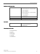
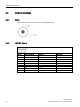
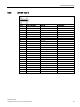
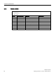
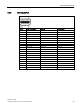
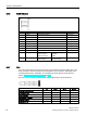
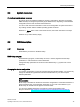
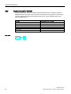
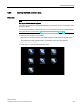
Table Of Contents
- SIMATIC ITP1000
- Warning notice system
- Preface
- Table of contents
- 1 Overview
- 2 Safety notes
- 3 Commissioning the device
- 4 Devise functions and operating the device
- 5 Device maintenance and repair
- 6 Technical specifications
- A Technical Support
- B Labels and symbols
- C Abbreviations
- Index

Technical specifications
6.4 External interfaces
SIMATIC ITP1000
76 Operating Instructions, 01/2017, A5E37340160-AA
6.4.6
RJ45 Ethernet
Pin no.
Short description
Meaning
Input/output
1
BI_DA+
Bi-directional data A+
Input/output
2
BI_DA-
Bi-directional data A-
Input/output
3
BI_DB+
Bi-directional data B+
Input/output
4 BI_DC+ Bi-directional data C+ Input/output
5
BI_DC-
Bi-directional data C-
Input/output
6 BI_DB- Bi-directional data B- Input/output
7
BI_DD+
Bi-directional data D+
Input/output
8
BI_DD-
Bi-directional data D-
Input/output
S
Shielding
–
LED 1 OFF
Lights up green
Lights up orange
10 Mbps
100 Mbps
1 Gbps
–
LED 2 Lights up green
Flashes green
Connection is up
indicates activity
–
6.4.7
UAJ
You can connect various audio devices to the UAJ connection (Universal Audio Jack). The
audio controller socket recognizes the pin assignment of the connector, depending on the
connected audio device. Information on connecting the audio devices can be found in
section "Connecting peripheral devices (Page 36)".
The pins of a 3.5 mm jack are assigned as follows depending on the audio device:
Tip
Ring 1
Ring 2
Sleeve
Headphone out (stereo)
L
R
-
GND
Line out (stereo)
L
R
-
GND
Line in (stereo)
L
R
-
GND
Microphone in (mono)
MIC
-
-
GND
Headset (OMTP)
L
R
MIC
GND
Headset (CTIA)
L
R
GND
MIC