
User Manual
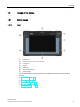
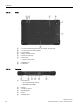
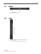
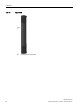
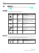
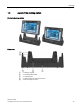
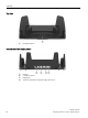
Table Of Contents
- SIMATIC ITP1000
- Warning notice system
- Preface
- Table of contents
- 1 Overview
- 2 Safety notes
- 3 Commissioning the device
- 4 Devise functions and operating the device
- 5 Device maintenance and repair
- 6 Technical specifications
- A Technical Support
- B Labels and symbols
- C Abbreviations
- Index

Overview
1.2 Design of the device
SIMATIC ITP1000
16 Operating Instructions, 01/2017, A5E37340160-AA
1.2.3
Status displays
The status displays (LEDs) are located on the front of the device, see section "Front
(Page 11)".
System LEDs
System LEDs indicate various operating states.
Symbol
Meaning
Colors
Meaning of colors
Rechargeable
battery
GREEN
ORANGE
RED
OFF
Battery is charged
Battery is being charged.
Battery capacity too low (only with battery op-
eration)
No battery available
Operation GREEN
ORANGE
GREEN flashing
ORANGE flashing
OFF
Mains operation
Battery operation
Mains operations, device is in sleep mode
Battery operation, device is in sleep mode
Device is switched off
Mass storage GREEN Access to the external memory (hard disk,
optical drive)
User program RED
GREEN
User program inactive
Active user program
The status display can be controlled from the
user program.
Card reader GREEN Card reader for SD cards and multimedia cards
is active
Wireless LED
The wireless LED relates both to WLAN and to Bluetooth. You may customize both functions
in the corresponding application during installation of the software.
Symbol
Meaning
Colors
Meaning of colors
WLAN/Bluetooth ORANGE
OFF
Radio connection switched on
Radio connection switched off