Industrial Thin Client ITC1200, ITC1500,___________________ Preface ITC1900, ITC2200 SIMATIC HMI HMI device Industrial Thin Client ITC1200, ITC1500, ITC1900, ITC2200 Operating Instructions 1 ___________________ Overview 2 ___________________ Safety instructions Installing and connecting the 3 ___________________ device 4 ___________________ Commissioning the device 5 ___________________ Assigning device parameters 6 ___________________ Configuring the server 7 ___________________ Operating the device
Legal information Warning notice system This manual contains notices you have to observe in order to ensure your personal safety, as well as to prevent damage to property. The notices referring to your personal safety are highlighted in the manual by a safety alert symbol, notices referring only to property damage have no safety alert symbol. These notices shown below are graded according to the degree of danger.
Preface Purpose of the operating instructions These operating instructions provide information based on the requirements defined by DIN EN 62079 for mechanical engineering documentation. This information relates to the place of use, transport, storage, mounting, use and maintenance.
Preface Scope of the operating instructions These operating instructions apply to the following devices: ● SIMATIC ITC1200 ● SIMATIC ITC1500 ● SIMATIC ITC1900 ● SIMATIC ITC2200 The designation "ITC (Industrial Thin Client)" encompasses all of the named devices.
Table of contents Preface ...................................................................................................................................................... 3 1 2 3 4 5 Overview.................................................................................................................................................... 9 1.1 Product description ........................................................................................................................9 1.
Table of contents 6 7 5.3.1 5.3.2 5.3.3 5.3.4 5.3.5 5.3.5.1 5.3.5.2 5.3.5.3 5.3.5.4 5.3.5.5 5.3.6 5.3.7 5.3.8 Access and structure................................................................................................................... 38 Device data ................................................................................................................................. 40 System settings...................................................................................................
Table of contents 8 9 A Device maintenance and repair ............................................................................................................... 97 8.1 Cleaning the device front .............................................................................................................97 8.2 Disabling the touch screen...........................................................................................................98 8.3 Calibrating the touch screen ...................
Table of contents Industrial Thin Client ITC1200, ITC1500, ITC1900, ITC2200 8 Operating Instructions, 04/2013, A5E03474888-02
1 Overview 1.1 Product description SIMATIC ITC - the high-performance local thin client solution Industrial Thin Clients are low-cost HMI terminals that provide local HMI functionality in plants spread over large areas. In this way, Industrial Thin Clients contribute to an improved overview, operability, and productivity of plants.
Overview 1.2 Product package Easy commissioning The Industrial Thin Client merely requires an IP address. For fast on-site commissioning and diagnostics, the SIMATIC ITC is equipped with a Setup Wizard optimized for touch operation. Alternatively, the Remote Configuration Center (RCC V2.0 or higher) management software enables easy, efficient remote configuration and diagnostics of one or more devices. Local software installation on the device is not necessary.
Overview 1.3 Layout of the devices 1.
Overview 1.3 Layout of the devices Rear view ① ② ③ ④ ⑤ 1.3.1 Rating plate Cover Interface designation Ground connection Fixing elements for strain relief Interfaces The following figure shows the interfaces on the device.
Overview 1.4 Accessories 1.4 Accessories Accessories are not included in the scope of delivery of the HMI device, but can be ordered on the Internet at Industry Mall (http://mall.automation.siemens.com). This section provides information on the scope of accessories available at the time these operating instructions were written. Protective films Designation Order No.
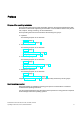
Overview 1.5 Typical applications Access to a server via "RDP". The Industrial Thin Client uses RDP (Remote Desktop Protocol) to access a server, such as an industrial PC or a PC. The following applications are also possible. ● WinCC/Web Navigator The Industrial Thin Client uses an Internet browser on the server to access the WinCC Web Navigator as a Web Navigator client. In this case, the operating system Windows Server 2003 or 2008 must be installed on the server.
Overview 1.5 Typical applications Access to a web server via "Web" The Industrial Thin Client displays applications and the content of a web server using the integrated web browser functionality . Web-based content may be diagnostic or user-specific web pages of an S7 controller (PROFINET), for example, or content from the Intranet/Internet.
Overview 1.6 Requirements 1.
Safety instructions 2.1 2 General safety instructions Open equipment and the Machinery Directive WARNING The device constitutes open equipment The device constitutes open equipment. This means that the device may only be installed in enclosures or cabinets which provide front access for operating the device. Access to the enclosure or cabinet in which the device is installed should only be possible by means of a key or tool and for trained and authorized personnel.
Safety instructions 2.2 Security information High frequency radiation NOTICE Unwanted operating states High-frequency radiation, for example from cellular phones, interferes with device functions and can cause device malfunction. This causes injury and damages the system. Avoid high-frequency radiation: Remove the sources of radiation from the vicinity of the device. Switch off radiating devices. Reduce the radio output of radiating devices.
3 Installing and connecting the device 3.1 Brief instructions - connecting and starting the device Procedure Step See also Place the device in the mounting cutout, and fasten the Mounting the device (Page 24) HMI device with the mounting clamps. Connect the equipotential bonding. Connection of equipotential bonding (Page 27) Connect the power supply. Connecting the power supply (Page 29) Connect PROFINET/Ethernet. Connecting device to the server (Page 30) Optional: Connect an external USB device.
Installing and connecting the device 3.2 Preparing for installation 3.2 Preparing for installation Select the mounting location of the HMI device Points to observe when selecting the mounting location: ● Position the HMI device so that it is not subjected to direct sunlight. ● Position the HMI device such that it is ergonomically accessible for the operator. Choose a suitable mounting height. ● Ensure that the air vents of the HMI device are not covered as a result of the mounting.
Installing and connecting the device 3.2 Preparing for installation 3.2.2 Checking the operating conditions Note the following aspects before installing the HMI device: 1. Familiarize yourself with the standards, approvals, EMC parameters and technical specifications for operation of the HMI device. This information is available in the following sections: – Certificates and approvals (Page 101) – Electromagnetic compatibility (Page 103) 2.
Installing and connecting the device 3.2 Preparing for installation NOTICE Damage due to overheating Convection through the device is reduced when it is installed at an angle. This means that the maximum permitted ambient temperature for operation is also reduced. With sufficient forced ventilation, you can operate the device when installed at an angle up to the maximum permitted ambient temperature for vertical installation. Otherwise, the approvals and warranty will be voided. 3.2.
Installing and connecting the device 3.2 Preparing for installation Degrees of protection The degrees of protection of the HMI device can only be guaranteed if the following requirements are met: ● Material thickness at the mounting cutout for IP65 degree of protection or Front face only Type 4X/Type 12 (indoor use only): 2 mm to 6 mm ● Permitted deviation from plane at the mounting cutout: ≤ 0.5 mm This condition must be fulfilled for the mounted HMI device.
Installing and connecting the device 3.3 Mounting the device 3.3 Mounting the device Position of the mounting clamps To achieve the degree of protection for the device, you need to comply with the mounting clamp positions listed below. The positions of the mounting clamps are marked by stamps on the cutouts. Fit mounting clamps in all the stamped cutouts. The following table shows the type, number and position of mounting clamps needed for the various devices.
Installing and connecting the device 3.3 Mounting the device Procedure Note Risk of guaranteed degree of protection not being met If the mounting seal is damaged or protrudes beyond the device, the degree of protection is not ensured. Checking the placement of the mounting seal To avoid leakage around the mounting cutout, do not install the mounting seal turned inside out. If the mounting seal is damaged, order a replacement seal.
Installing and connecting the device 3.4 Connecting the device 3.4 Connecting the device 3.4.1 Overview Requirement ● The device has been installed according to the information provided in these operating instructions. ● Always use shielded standard cables. For order information please refer to Industry Mall (http://mall.automation.siemens.com). Connection sequence Connect the device in the following sequence: 1. Equipotential bonding 2. Power supply 3. PROFINET/Ethernet 4.
Installing and connecting the device 3.4 Connecting the device 3.4.2 Connection of equipotential bonding Differences in electrical potential Differences in electrical potential can develop between spatially separated plant components. Such electrical potential differences can lead to high equalizing currents over the data cables and therefore to the destruction of their interfaces. Equalizing currents can develop if the cable shielding is terminated at both ends and grounded to different plant parts.
Installing and connecting the device 3.4 Connecting the device Wiring diagram ① ② ③ ④ ⑤ ⑥ ⑦ ⑧ Ground connection on the device, example Equipotential bonding conductor cross-section: min. 4 mm2 Control cabinet Equipotential bonding conductor cross-section: min.
Installing and connecting the device 3.4 Connecting the device 3.4.3 Connecting the power supply Configuration graphic The figure below shows the connection between the device and the power supply. '& 9 *1' Note when connecting The mains terminal for connecting the power supply is contained in the accessory kit. The mains terminal is designed for cables with a maximum cross-section of 1.5 mm².
Installing and connecting the device 3.4 Connecting the device Safe power supply NOTICE Device malfunction If the supply voltage is outside the specified range, device malfunctions cannot be ruled out. Use only 24 VDC power supply units with safe electrical isolation in accordance with IEC 60364-4-41 or HD 60364-4-41, for example, to SELV / PELV standard. Applies to non-isolated plant configurations: Connect the "GND" terminal of the 24 VDC power supply to the equipotential bonding.
Installing and connecting the device 3.5 Installing strain relief 3.4.5 Connecting a USB device You can connect the following devices to the USB port: ● Mouse ● Keyboard ● Industrial USB Hub 4 ● USB memory devices The device only supports USB storage devices that have been formatted with the FAT16/FAT32 or NFTS file system.
Installing and connecting the device 3.
Commissioning the device 4.1 4 Switching on and testing the device Procedure Proceed as follows: 1. Switch on the power supply. Information regarding the included free software is displayed during startup. If the device fails to start, you may have crossed the wires on the mains terminal. Check the connected wires and change their connection. Additional information is available in the configuration settings, Section Basics (Page 50). Make sure that you observe the warning at the end of the section.
Commissioning the device 4.2 Interrupting and restoring a connection 4.2 Interrupting and restoring a connection Introduction The connection to the server can be interrupted in several ways: ● The server is offline or has has not completed its startup sequence. ● The password is incorrect. ● A firewall is blocking server access. ● The SINUMERIK server does not support the Industrial Thin Client, for example, if the firmware on the server is outdated.
Assigning device parameters 5.1 5 Possible applications Possible applications The Industrial Thin Client can fulfill the following functions as an operator terminal: ● Access to an HMI device as a Sm@rtServer client via the WinCC Sm@rtServer option. ● Access as a client via the "RDP" protocol (Windows programs). ● Access as a client via the "VNC" protocol (Windows programs). ● Access to a SINUMERIK PCU or NCU as a SINUMERIK Thin Client Unit (TCU). ● Access as a web client to a web server, e.g.
Assigning device parameters 5.2 Opening the configuration Procedure on the device 1. Press the "Start menu" symbol in the task bar. 2. Select the menu entry "Configuration". At first, all configuration settings are displayed in the "All" submenu. Detailed information is available in the section "Access and structure (Page 38)". 3. Go left to another submenu, for example "Information". The device information is displayed (see section "Device data (Page 40)"). 4.
Assigning device parameters 5.2 Opening the configuration NOTICE Unintended reactions of the device Two people can edit the configuration settings simultaneously: locally on the device and via remote configuration. The most recently saved settings are the valid settings at any given time (blue "Save" symbol). Organize access to the configuration settings in such a way that only one person can edit the configuration settings at one time.
Assigning device parameters 5.3 Configuration settings of the device 5.3 Configuration settings of the device 5.3.1 Access and structure Structure The following figure shows the configuration settings in the "Configuration" Start menu.
Assigning device parameters 5.3 Configuration settings of the device ● Desktop settings under "Desktop": – Taskbar – On-screen keyboard – Background image ● Application settings under "Applications": Web browser settings Note Forced termination of connection When you change and save the configuration settings, all open client-server connections are terminated and all open programs are closed without a confirmation prompt.
Assigning device parameters 5.3 Configuration settings of the device See also 5.3.2 Network settings (Page 46) System settings (Page 41) Password settings (Page 58) Setting up startup connection (Page 56) Device data The following figure shows the device data in the Start menu "Configuration > Information". The device data identify the device uniquely and are shown here for informational purposes only. You edit the device data in the System settings (Page 41) and Network settings (Page 46).
Assigning device parameters 5.3 Configuration settings of the device 5.3.3 System settings Introduction The following figure shows the system settings in the Start menu "Configuration > System".
Assigning device parameters 5.3 Configuration settings of the device Specifying device name In the "Device information" area, specify a name for the Industrial Thin Client in "Device name". This name will allow the administrator to identify the device. The device name will be displayed at the following places: ● In the title bar of the configuration settings ● In the case of Remote configuration of several devices (Page 66), in the device window that lists the Industrial Thin Clients found in the network.
Assigning device parameters 5.3 Configuration settings of the device Set the "Screen brightness". You can also use the system settings to "Calibrate touch screen" (see section "Calibrating the touch screen (Page 98)"). If you select the "Right mouse click" option, each contact on the touch screen lasting more than 2 seconds will be interpreted as a right-click.
Assigning device parameters 5.3 Configuration settings of the device Save and restore the configuration file You back up the configuration file of the device either directly on the device via USB or from a PC via Remote configuration of several devices (Page 66). The configuration file contains all device-specific configuration settings with the exception of the background image and the touch calibration.
Assigning device parameters 5.3 Configuration settings of the device Note Faulty touch operation The touch screen must be recalibrated. Procedure: 1. Touch the "Restore to factory settings" button. The "Resetting to factory defaults" message is shown on the touch screen. The device reboots automatically if you confirm this message. 2.
Assigning device parameters 5.3 Configuration settings of the device 5.3.4 Introduction Network settings The following figure shows the network settings in the Start menu "Configuration > Network". You can perform the following actions: ● Specify network parameters ● Assign network parameters dynamically ● Use DNS server ● Check valid settings ● Specify speed and mode of the connection Note These network settings are not relevant for the SINUMERIK connection.
Assigning device parameters 5.3 Configuration settings of the device Specify network parameters You assign the network parameters either statically or dynamically: ● If "Assign IP address automatically (DHCP)" is not selected, assign a valid static IP address, subnet mask, and default gateway.
Assigning device parameters 5.3 Configuration settings of the device Use DNS server You can manually enter the IP address of the DNS server under "DNS server". If you select the "Automatically assign DNS server" option, the manual IP address is overwritten by an IP address assigned by the DHCP server. This requires that the "Assign IP address automatically (DHCP)" option is also selected.
Assigning device parameters 5.3 Configuration settings of the device Specify speed and mode of the connection The device detects the data rate and the connection mode of its physical connection partner and adapts itself automatically. The "Set automatically" option is therefore selected by default. The other parts of the dialog are disabled. A switch can also be a connection partner. You can, however, set the data rate and the connection mode manually.
Assigning device parameters 5.3 Configuration settings of the device 5.3.5 Connections 5.3.5.1 Basics Introduction Users can connect from the Thin Client to different servers.
Assigning device parameters 5.3 Configuration settings of the device Special features with SINUMERIK Note The SINUMERIK connection is configured automatically through the SINUMERIK system network and therefore does not need any connection settings or a connection password. Note PROFINET basic functions The SINUMERIK connection supports only the PROFINET basic services.
Assigning device parameters 5.3 Configuration settings of the device Factory default settings ● Administrator password "admin" ● "Obtain IP address automatically (DHCP)" Note Misuse The factory-set administrator password for all devices is "admin". This means that unauthorized persons have free access to the configuration settings. After initial commissioning or restoring of the factory settings, you should log on with "admin" and assign a new administrator password.
Assigning device parameters 5.3 Configuration settings of the device 5.3.5.2 Setting up client-server connections Structure of the tab The following figure shows the list of client-server connections in the Start menu "Configuration > Connections". At the bottom are buttons for editing a selected client-server connection. Buttons The buttons have the following functions: ● "New": creates a new client-server connection. ● "Edit": opens the connection settings of the client-server connection.
Assigning device parameters 5.3 Configuration settings of the device 5.3.5.3 Connection settings By way of example, the following figure shows the connection settings for an RDP connection in the Start menu "Configuration > Connections". You select a client-server connection, or create a new one. The following connection settings can be specified: Note Grayed-out fields Not all connection settings are available for each type of connection (exception: RDP).
Assigning device parameters 5.3 Configuration settings of the device ● In "URL" ("Web" connection type only), you specify an Internet address at which the web server can be reached. ● In "Server port", the default port is set. RDP: 3389, Sm@rtServer/VNC: 5900. ● In "Start program" (RDP only), you specify the software program that is automatically started on the server with this RDP connection. ● In "Redundant 2nd server" (RDP only), you select a second, previously configured RDP connection.
Assigning device parameters 5.3 Configuration settings of the device ● If you select the "Connect USB as drive" option (RDP only), you can access a USB memory device connected to the Industrial Thin Client on the touch screen. The USB data are transferred to the server and displayed there in Windows Explorer for the devices. For additional information, refer to the section "Operating a USB memory device (Page 95)".
Assigning device parameters 5.3 Configuration settings of the device 5.3.5.5 PROFINET basic functions Introduction The PROFINET basic functions help to diagnose the device using standard mechanisms. The required diagnostics functions are available, for example, in STEP 7. Functions As of SIMATIC Manager V5.4, SP2, the PROFINET basic functions offer the following functions: ● As soon as the device is connected to PROFINET, it is displayed as an available device in the Lifelist in SIMATIC Manager.
Assigning device parameters 5.3 Configuration settings of the device 5.3.6 Password settings Introduction The following figure shows the password settings in the Start menu "Configuration > Passwords". Note Forced termination of connection When you save the changed configuration settings, all open client-server connections are terminated and all open programs are closed without a confirmation prompt. The configured autostart connections are re-established.
Assigning device parameters 5.3 Configuration settings of the device To edit the configuration settings, follow these steps: 1. Move the blue circle (slider) "Logon" in the toolbar to the right. 2. Enter the administrator password. 3. Click the "Logon" button to close the dialog. You are logged on as administrator. Logging off as an administrator To protect the configuration settings from unauthorized access from the outside, follow these steps: 1.
Assigning device parameters 5.3 Configuration settings of the device After factory settings are restored, a saved configuration file can be transferred back to the device. Once the configuration file is restored, the password contained therein will be valid after the device is restarted. Change the password if necessary, and make a note of it. Closing connections with connection password You can specify a password for terminating a client-server connection in the Start menu "Configuration > Passwords".
Assigning device parameters 5.3 Configuration settings of the device 5.3.7 Desktop settings Introduction The following figure shows the desktop settings in the Start menu "Configuration > Desktop". You can make the following settings: ● Position of the taskbar ● Display of the taskbar ● Menu entries in the Start menu ● Size and position of the on-screen keyboard ● Background image Specifying the position of the taskbar Touch one of the 6 buttons on the displayed touch screen.
Assigning device parameters 5.3 Configuration settings of the device Specifying the display of the taskbar Note Faulty touch calibration If the touch screen has not been calibrated or has been calibrated improperly, you will only be able to re-display a hidden taskbar by means of a connected external mouse. Make sure that the touch screen of your HMI device has been calibrated correctly. ● "Always in front" (default setting) The taskbar is displayed after the device is switched on.
Assigning device parameters 5.3 Configuration settings of the device Note Required properties of background images Format: PNG, JPG, JPEG File size: max. 5 MB Resolution: Maximum 1920 x 1080 for ITC2200 Colors: Maximum 16777216 Display of the background image The background image is always stretched to fit the screen resolution, even when this distorts it and grossly enlarges it.
Assigning device parameters 5.3 Configuration settings of the device 5.3.8 Application settings Introduction Additional, configurable application programs (software applications) can run on the Industrial Thin Client. The web browser is currently the only application. The following figure shows the web browser settings in the Start menu "Configuration > Applications".
Assigning device parameters 5.3 Configuration settings of the device ● If "No proxy" is selected, there is no proxy server request, and a direct connection to the Internet or an intranet will be established instead. ● Under "Port", specify the internal port at which the proxy server can be reached: The default is 8080. ● In "Home page", specify an Internet address that will be called automatically when the web browser starts.
Assigning device parameters 5.4 Remote configuration of several devices Adjusting the display in the web browser You can enlarge or reduce the display in the web browser: ● Use the key combination <+> to enlarge the display. ● Use the key combination <-> to reduce the display. Note Depending on the keyboard you are using, it may be necessary to press the Shift key to access the "+" and "-" keys. In this case, use <+> to enlarge the display and <-> to reduce it.
Assigning device parameters 5.4 Remote configuration of several devices 5.4.2 Installation Requirements The following requirements must be met for operation: ● The Industrial Thin Client is in a PROFINET or Ethernet network. ● At least 1 network adapter is installed in the PC.
Assigning device parameters 5.4 Remote configuration of several devices 4. Accept the license agreement and close the dialog with "Next". The "Set PG-PC Interface" dialog appears. 5. Select a network adapter for the network, and close the dialog with "OK". The network adapter can be changed later via the Windows system settings. 6. Complete the installation at the end of the installation process with the "Finish" button. We recommended that you reboot the PC.
Assigning device parameters 5.4 Remote configuration of several devices 5.4.4 Operation 5.4.4.1 Overview of remote operation User interface No.
Assigning device parameters 5.4 Remote configuration of several devices 3. Use drag-and-drop to move devices to the new "Machine1" folder in the device tree ④. The folder is saved retentively in the local device memory. As a result, the device is always assigned to this folder. Note Devices of earlier versions The firmware version V1.x does not support folders. Therefore, older devices cannot be assigned and always appear in the "Thin Clients V1.X" folder.
Assigning device parameters 5.4 Remote configuration of several devices Save the configuration file remotely and restore it The configuration file contains all device-specific configuration settings with the exception of the background image and the touch calibration. Save the configuration file of a device on the central PC. From there, you can restore the configuration file to a device: ● Use the "Save" button to back up the configuration file for the device on the PC.
Assigning device parameters 5.4 Remote configuration of several devices Editing configuration settings of several devices synchronously 1. Select one or more devices in the device window ④. The configuration window ⑤ then displays the following: – One device selected: the same configuration settings as on the device (see "Opening the configuration (Page 35)"). You navigate via the submenu on the left. – Several devices selected: configuration settings in a table.
Assigning device parameters 5.4 Remote configuration of several devices Special features for connections If you select "Connections" in the configuration window ⑤, the currently configured clientserver connections for each selected device are transferred one after the other and displayed row-by-row in the configuration window (complete connection list). If a device has exactly the connection displayed in the row, the relevant column receives a check mark.
Assigning device parameters 5.4 Remote configuration of several devices 5.4.4.2 Perform action Procedure Note Actions only one after the other You can only perform one action after another on a device. Before performing an action on a device, wait until the actions on all selected devices have been completed. Proceed as follows to perform an action: 1. Select one or more devices in the device window. To select all devices, touch the "Select all" icon. 2.
Assigning device parameters 5.4 Remote configuration of several devices 5.4.4.3 Status A status symbol and monitor icon is displayed in the device tree to the right next to the device name. ● The status describes the outcome of the last action for each device. ● The monitor icon displays the firmware version of the device. ● A question mark means no version information is available, for example, if the device cannot be found.
Assigning device parameters 5.4 Remote configuration of several devices 5.4.4.4 Assigning the IP address In the "IP" tab, assign new IP addresses for one or more devices. Note No connection between client and server If you change the IP address, an RDP, VNC/Sm@rtServer, or SINUMERIK connection may be interrupted. Communication between the device and server is then not possible. IP address conflicts If you manually assign IP addresses, make sure that different devices do not have the same IP address.
Assigning device parameters 5.4 Remote configuration of several devices 5.4.5 Backing up remote configuration SSH configuration service The device is factory set to be remotely configured via the SSH configuration service, which enables remote configuration. NOTICE Impairment of security due to SSH This means unauthorized personnel can log on via SSH and have free access to the devices and client-server connections.
Assigning device parameters 5.4 Remote configuration of several devices 5.4.6 Assigning a key Generating a new key pair A pair of private and public keys provides security for remote updating and remote configuration. The public key is installed by default on the device. If you install the remote configuration on a PC, the private default key is stored in the device directory. NOTICE Danger of data misuse The default private key file is the same for each device.
Assigning device parameters 5.4 Remote configuration of several devices 5.4.7 Basic settings You make the basic settings for remote configuration via the menu bar and the Windows system settings. 1. Select "Basic Settings" in the menu bar. 2. Under "Global Data Directory", use the "Browse" button to specify the root directory in which a separate device directory is created for each device.
Assigning device parameters 5.
Configuring the server 6.1 RDP 6.1.1 RDP overview 6 Introduction RDP, "Remote Desktop Protocol", is a protocol that the Industrial Thin Client uses to access a server with a Windows operating system, e.g., Windows Server or Windows XP. The Industrial Thin Client can access all programs running on the server, if the programs have been enabled for remote access. The following statements for Windows XP also apply to Windows 7.
Configuring the server 6.1 RDP Licensing Windows XP Professional and Windows 7 You do not require any licenses on your device under Windows 7 to access the server. Only one license on the PC for your operating system, e.g. Windows 7. You do not require any additional licenses on the server for Remote Desktop. Only one screen can be operated for Remote Desktop with the Windows XP Professional operating systems. You can operate either the screen on the server or the touch screen on the device.
Configuring the server 6.2 VNC Keyboard language with Windows XP Professional A German-language on-screen keyboard and an English-language on-screen keyboard are available on the device. Set the keyboard language on the device so that it matches the keyboard language on the server. If the keyboard languages on the device and the server are different, the keys pressed on the device keyboard will not be interpreted correctly on the server.
Configuring the server 6.3 Sm@rtServer 6.3 Sm@rtServer Introduction With the SIMATIC WinCC Sm@rtServer option, HMI devices communicate with each other via PROFINET. The WinCC option thus enables client/server configurations for distributed operator stations in a plant. If the SIMATIC WinCC Sm@rtServer option is installed on an HMI device, for example, on an MP 377 or Comfort Panel, the Industrial Thin Client can access the running project via Ethernet. In this case, the HMI device is the server.
Configuring the server 6.4 SINUMERIK 6.4 SINUMERIK Introduction The DHCP server is enabled on each SINUMERIK server by default. The SINUMERIK system network therefore configures itself dynamically via the DHCP protocol. Additional information is available in the "SINUMERIK manual "Operator components and networking" (6FC5397-1AP10-5AA0) (http://www.automation.siemens.com/doconweb/)".
Configuring the server 6.
Operating the device 7.1 7 Overview Introduction If you are using the device to access a server, the screen display of the server is shown on the device. You operate the server screen from the device. Operator input options The following operator input options are available, depending on the peripherals that are connected to your device: ● Touch screen You activate operating elements by touching them with your finger. To double-click them, touch an operating element twice in succession.
Operating the device 7.2 Front operator controls On-screen display for remote access to a server The server screen is displayed as a full screen. Additional information is available in the configuration settings, Section "Connections (Page 50)". Monitoring mode If you access a device on which only monitoring mode has been configured for Sm@rtServer access, you can only monitor the device; you cannot intervene for control purposes.
Operating the device 7.3 Operating the taskbar Note when operating NOTICE Damage to the touch screen Operation of the touch screen in the following ways will reduce its service life up to and including total failure: Touching it with a pointed or sharp object Abrupt impact with solid objects Use only your finger or a touch pen to touch the touch screen 7.3 Operating the taskbar 7.3.
Operating the device 7.3 Operating the taskbar If you touch the icon, a list of started client-server connections appears. You use the "Favorites" icon to start a client-server connection. The icons have the following meaning: ● Green check mark: Client-server connection is running.
Operating the device 7.3 Operating the taskbar 7.3.2 Starting a connection Overview From the Industrial Thin Client, you can establish a connection to a server with the configured connection settings. The following connection types are supported: ● RDP ● Sm@rtServer/VNC ● SINUMERIK: Bootloader and Viewer are started. A selection menu with the "Open" command is displayed. ● Web: besides the web connection, additional web settings are required for the web browser that displays the web connection.
Operating the device 7.3 Operating the taskbar Special features SINUMERIK The automatic assignment of the IP address is activated temporarily in the network settings. The SINUMERIK Bootloader briefly displays the IP address of the server currently connected. The SINUMERIK server first starts the SINUMERIK Bootloader, which loads SINUMERIK Viewer with the configuration file on the Industrial Thin Client. Afterwards the SINUMERIK user interface is displayed on the Industrial Thin Client.
Operating the device 7.3 Operating the taskbar 7.3.4 Terminating a connection Introduction You can terminate a client-server connection as follows: ● Using the "Close" menu command (see below). ● For more options refer to "Special features". Procedure Proceed as follows to terminate an active client-server connection: 1. Touch the "Connection list" icon in the taskbar. A list of all started client-server connections opens. 2. Choose the "Close" menu command next to the connection. 3.
Operating the device 7.4 Operating the on-screen keyboard 7.4 Operating the on-screen keyboard On-screen keyboard If you have not connected an external keyboard to the device, use the on-screen keyboard for inputs, e.g., in the configuration settings. If you activate an IO field when accessing a WinCC flexible or WinCC project on a server, the on-screen keyboard is displayed automatically.
Operating the device 7.5 Operating a USB memory device Windows key The "Win" key corresponds to the Windows key on a mechanical keyboard. You use this key to open the Windows Start menu. Number pad The on-screen keyboard has a separate number pad that you open with the "NUM" key. If you have connected an external keyboard, you cannot make any entries via the number pad of the external keyboard.
Operating the device 7.5 Operating a USB memory device Procedure 1. Insert the USB memory device in the USB port on the device. 2. Choose "Settings > USB devices" in the taskbar. A media explorer opens. 3. Touch the "View details" icon in the menu bar. 4. Open the desired folder in the tree menu on the left. Its content is displayed in the window on the right. 5. You can cut, copy, paste, and delete files via the menu bar. 6.
Device maintenance and repair 8.1 8 Cleaning the device front Introduction The device is designed for low-maintenance operation. Nevertheless, you should clean the touch screen periodically. Requirement ● Damp cleaning cloth ● Washing up liquid or foaming screen cleaning agent Procedure WARNING Unintentional response If you clean the touch screen while it is switched on, you could initiate operator controls by mistake.
Device maintenance and repair 8.2 Disabling the touch screen 8.2 Disabling the touch screen Cleaning You can clean the touch screen of the HMI device when it is switched on and a connection is active. To do this you must disable the touch screen. WARNING Unintentional response If you clean the touch screen while it is switched on, you could initiate operator controls by mistake.
Device maintenance and repair 8.4 Spare parts and repairs 8.4 Spare parts and repairs Repairs In case of repair, the device must be shipped to the Return Center in Fürth. The address is: Siemens AG Industry Sector Returns Center Siemensstr. 2-4 90766 Fürth Germany For additional information, refer to the Internet at "Spare parts and repairs (http://support.automation.siemens.com/WW/view/en/16611927)".
Device maintenance and repair 8.
Technical specifications 9.1 9 Certificates and approvals Approvals NOTICE Applicability The following overview shows possible approvals. The device itself is certified only as shown on the rear of the device.
Technical specifications 9.1 Certificates and approvals Approved for use in ● Class I, Division 2, Group A, B, C, D or ● Class I, Zone 2, Group IIC or ● non-hazardous locations FM Approval FM APPROVED Factory Mutual Research (FM) conforming to ● Approval Standard Class Number 3611, 3600, 3810 ● ANSI/ISA 61010-1 ● CSA C22.2 No. 213 ● CSA C22.2 No. 1010.
Technical specifications 9.2 Directives and declarations 9.2 Directives and declarations 9.2.1 Electromagnetic compatibility Introduction The device fulfills the requirements of the EMC law of the single European market, among others. EMC-compliant device installation EMC-compliant installation of the device and the use of interference-proof cables provide the bases for trouble-free operation. The description "Guidelines for Interference-free Setup of PLCs" is also valid for the device installation.
Technical specifications 9.2 Directives and declarations 9.2.2 ESD guideline What does ESD mean? An electronic module is equipped with highly integrated components. Due to their design, electronic components are highly sensitive to overvoltage and thus to the discharge of static electricity. Such electronic components or modules are labeled as electrostatic sensitive devices.
9ROWDJH Technical specifications 9.2 Directives and declarations >N9@ > @ 5HODWLYH KXPLGLW\ ① ② ③ Synthetic materials Wool Antistatic materials such as wood or concrete NOTICE Grounding measures There is no equipotential bonding without grounding. An electrostatic charge is not discharged and may damage the ESD. Protect yourself against discharge of static electricity.
Technical specifications 9.3 Dimensional drawings 9.3 Dimensional drawings 9.3.
Technical specifications 9.3 Dimensional drawings 9.3.
Technical specifications 9.3 Dimensional drawings 9.3.
Technical specifications 9.3 Dimensional drawings 9.3.
Technical specifications 9.4 Technical specifications 9.4 Technical specifications 9.4.1 General technical specifications Weight HMI devices ITC1200 Weight without packaging ITC1500 3.4 kg ITC1900 5.2 kg 6.5 kg ITC2200 7.1 kg Display HMI devices ITC1200 Type Active display area ITC1500 LCD TFT with extended viewing angle LCD TFT ITC2200 LCD TFT with extended viewing angle 12.1'' 15.4'' 18.5'' 21.5'' 261.1 x 163.2 mm 331.2 x 207 mm 409.8 x 230.4 mm 495.6 x 292.
Technical specifications 9.4 Technical specifications Memory HMI devices ITC1200 Main memory ITC1500 ITC1900 ITC2200 512 MB DDR3 SDRAM Memory 2 GB SSD Interfaces HMI devices ITC1200 Ethernet (PROFINET basic functionality) ITC1500 ITC1900 1 x RJ45 10/100/1000 Mbps USB 2.0 1 ITC2200 2 x Host 1 USB type A, maximum load 500 mA, equivalent to USB standard 2.0 Power supply HMI devices ITC1200 ITC1500 ITC1900 Rated voltage 24 V DC Permissible voltage range +19.2 V to +28.
Technical specifications 9.4 Technical specifications 9.4.2 Performance data Performance values The performance depends on the network capacity in your system. With the SIMATIC WinCC Sm@rtServer option, the performance varies within the values specified in the WinCC documentation. See also FAQ 25576569 (http://support.automation.siemens.com/WW/view/en/25576569) 9.4.3 Ambient conditions 9.4.3.
Technical specifications 9.4 Technical specifications 9.4.3.2 Operating conditions Mechanical and climatic conditions of use The HMI device is intended for use in locations protected from the effects of the weather.
Technical specifications 9.4 Technical specifications Testing mechanical ambient conditions The following table provides information on the type and scope of tests for mechanical ambient conditions. Tested for Test standard Comments Vibrations Vibration test in accordance with IEC 60068, part 2–6 (sinusoidal) Type of vibration: Frequency cycles at a rate of change of 1 octave/minute. 5 Hz ≤ f ≤ 8.4 Hz, constant amplitude 0.075 mm 8.
Technical specifications 9.4 Technical specifications Pulse-shaped interference The following table shows the electromagnetic compatibility of modules with regard to pulseshaped interference. This requires the device to meet the specifications and directives for electrical installation.
Technical specifications 9.4 Technical specifications Emission of radio interference The following table shows the unwanted emissions from electromagnetic fields in accordance with EN 55016, Limit Value Class A, Group 1, measured at a distance of 10 m. From 30 to 230 MHz < 40 dB (μV/m) quasi-peak From 230 to 1000 MHz < 47 dB (μV/m) quasi-peak Additional measures Before you connect a device to the public network, ensure that it is compliant with Limit Class B in accordance with EN 55022. 9.4.3.
Technical specifications 9.5 Description of the ports 9.5 Description of the ports 9.5.1 Power supply Plug connector, 2-pin The following table shows the pin assignment of the power supply. Pin 9.5.2 Assignment 1 +24 VDC 2 GND 24 V USB USB socket The following table shows the pin assignment of the USB port. Pin Assignment 1 +5 VDC, out, max.
Technical specifications 9.5 Description of the ports 9.5.3 PROFINET (LAN) 10/100/1000 Mb Models of 15" and more have this interface.
Technical Support A.1 A Service and support You can find additional information and support for the products described on the Internet at the following addresses: ● Technical support (http://www.siemens.de/automation/csi_en_WW) ● Support request form (http://www.siemens.com/automation/support-request) ● After-sales information system for SIMATIC PC / PG (http://www.siemens.com/asis) ● SIMATIC Documentation Collection (http://www.siemens.
Technical Support A.
B Abbreviations CAL Client Access License (Windows Server) DC Direct Current DHCP Dynamic Host Configuration Protocol DNS Domain Name System DP Distributed I/O ESD Components and modules endangered by electrostatic discharge EMC Electromagnetic Compatibility EN European standard ESD Components and modules endangered by electrostatic discharge GND Ground HF High Frequency HMI Human Machine Interface HTTP Hypertext Transfer Protocol IEC International Electronic Commission IP Int
Abbreviations Industrial Thin Client ITC1200, ITC1500, ITC1900, ITC2200 122 Operating Instructions, 04/2013, A5E03474888-02
Glossary Browser A browser is a computer program that is used to start Web sites in the Internet. Client-server system A client/server system is a network structure in which the resources are offered by a central server that the workstations (clients) can access. Degree of protection The degree of protection specifies the suitability of electronic equipment for a variety of ambient conditions – and the protection of persons against potential danger when using this equipment.
Glossary Ethernet Ethernet is a fixed-cable data network technology for local area networks (LANs). Ethernet enables data transfer in the form of data frames between all devices that are connected in a local area network, for example, computers, printers. HMI device An HMI device is a device used for the operation and monitoring of machines and plants. The statuses of the machine or plant are indicated by means of graphic elements or by indicator lamps on the HMI device.
Glossary Remote Desktop Protocol (RDP) RDP enables network access to applications that are executed on a Windows Terminal Server. In this process the RDP regulates transmission of screen content and keyboard and mouse inputs over the network. Screen Form of the visualization of all logically related process data for a plant. The visualization of the process data can be supported by graphic objects.
Glossary Industrial Thin Client ITC1200, ITC1500, ITC1900, ITC2200 126 Operating Instructions, 04/2013, A5E03474888-02
Index A Abbreviation, 121 Administrator, 59 Administrator password, 39 Ambient conditions Climatic, 114 Mechanical, 113 Test, 114 Application, 13 RDP, 14 SINUMERIK, 14 Sm@rtServer, 13 VNC, 14 Web, 15 Applications, Approval for Australia, 102 Approvals, 101 Auto-hide the taskbar, 62 Automatic connection establishment, 34 B Background image, 62 Basic knowledge Required, 3 Bottom view, 11 Components sensitive to electrostatic charge, 104 Computer, 121 Conductor cross-section, 29 Equipotential bonding, 27 Co
Index Dewing, 112 Disabling, 98 Touch screen, 98 Display HMI devices, 110 Displaying device data, 40 Disposal, 4 Disturbance Pulse-shaped, 115 Sinusoidal, 115 Documentation Enclosed, 20 E EC Declaration of Conformity, 101 Electrical Safe separation, 30 Electrical potential difference, 27 Emission, 116 Equipotential bonding Cable, 28 Connecting, 27 Requirements, 27 Wiring diagram, 28 Equipotential bonding rail, 28 ESD, 104 ESD guidelines, 104 Establishing the connection, 34 Expert mode SSH configuration se
Index Storage conditions, 112 Transport conditions, 112 Memory HMI devices, 111 Monitoring mode, 88 Mounting Device, 25 EMC-compliant, 103 Mounting clamp Mounting, Mounting cutout Compatibility to other HMI devices, 23 Dimensions, 23 Preparing, 23 Mounting location, 20 Mounting position, 21 Multiple touch, 87 N Network settings, 46 Non-isolated plant configuration, 30 O On-screen keyboard, 94 Operating instructions Purpose of, 3 Scope, 4 Operating right, 88 Operator controls, 88 Operators, 3 P Password,
Index Multiple touch, 87 Preventing inadvertent operation, 97 Rated load, 31 Storage, 112 Touch screen, 89 Transport, 112 Unintentional response, 97 USB port, 31 Saving, 71 Configuration file, 71 Screen settings, 42 Security information, 18 Server, 13 Configuration, Interrupting the connection, 34 Restoring the connection, 34 Service packages, 13 Settings, 40 Application settings, 64 Changing the administrator password, 59 Check valid settings, 48 Displaying device data, 40 Editing configuration settings,
Index In industry, 103 In residential areas, 103 With additional measures, 113 Use DNS server, 48 V View, 11 VNC, 83 Application, 14 W Web Application, 15 Web browser, 64 Layout, 66 Weight HMI devices, 110 Windows Server, 81 Licensing, 81 Wiring diagram Equipotential bonding, 28 Industrial Thin Client ITC1200, ITC1500, ITC1900, ITC2200 Operating Instructions, 04/2013, A5E03474888-02 131
Index Industrial Thin Client ITC1200, ITC1500, ITC1900, ITC2200 132 Operating Instructions, 04/2013, A5E03474888-02