
Specifications


CP143 H1 / TCP/IP manual Commissioning
Rev. 00/07 6-1
6 Commissioning
6.1 Plug-in slots in the PLC
No configuration settings are required before the module is installed.
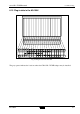
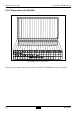
The following diagrams indicate possible slots (indicated by means of the grey squares) where the
CP143 H1 / TCP/IP may be installed into the different PLC frames.
6.1.1 Plug-in slots in the AG-115U
Fig. 6-1:Plug-in slots in the AG-115U
The grey squares indicate the locations where the CP143 H1 / TCP/IP adapter may be installed.
Q with the IM 304 / 314 interface