IP-Module IP-Module CFVA-IP IP-Module CVVA-IP User manual Issue 07/2005 Fire Safety & Security Products Siemens Building Technologies
Equipment availability and technical specifications subject to change without notice. Data and design subject to change without notice. Supply subject to availability. © Copyright by Siemens Building Technologies AG Wir behalten uns alle Rechte an diesem Dokument und an dem in ihm dargestellten Gegenstand vor.
Contents 1 Introduction .............................................................................................5 2 General Safety Precautions ...................................................................6 3 3.1 3.2 Ordering data...........................................................................................7 Ordering data for IP-Module CFVA-IP ......................................................7 Ordering data for IP-Module CVVA-IP ..............................................
Introduction 1 Introduction Thank you for deciding to buy this IP-Module. We wish you every success in using this product. If you have any questions about the product, please contact your local SIEMENS branch office. This IP-Module allows you to display live video images from a dome camera on your PC via an internet connection. The live video images are transmitted via a TCP/IP based network and displayed using an http browser (e.g. Netscape 7.0, Mozilla or Internet Explorer).
General Safety Precautions 2 General Safety Precautions Read these instructions carefully before connecting the camera and the IPModule in order to avoid damage caused by improper installation or use. Installation may be done only by authorized personnel according to the local safety regulations. Operate the camera and the IP-Module only with the designated voltage. Follow the safety instructions for the camera and for the IP-Module.
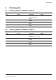
Ordering data 3 Ordering data 3.1 Ordering data for IP-Module CFVA-IP Type CFVA-IP Item no. 2GF1086-8AL PSU230-12 2GF1800-8BE CAPA2410-P230 2GF1800-8BJ 3.2 Description Weight IP-Module for 12 V DC / 24 0.40 kg V DC indoor fix dome camera Extra accessories, not included in the standard supply! 12 V DC camera power 0.12 kg supply 24 V AC camera power 0.30 kg supply Ordering data for IP-Module CVVA-IP Type CVVA-IP Item no.
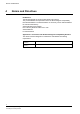
Norms and Directives 4 Norms and Directives EU Directive The following applies for the device described in this manual: The product satisfies the requirements of the EU Electromagnetic Compatibility Directive 89/336/EEC. The EU declarations of conformity can be made available to the relevant authorities by: Siemens Building Technologies Fire & Security Products GmbH & Co.
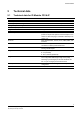
Technical data 5 Technical data 5.1 Technical data for IP-Module CFVA-IP Electrical supply Power requirement Operating temperature range Storage temperature range Dimensions (H x Ø) Weight Material System requirements Protocols Installation Network connection Image formats Image transmission Security Hardware 12 V DC/24 V AC max. 6.0 W -10 – +45 °C, max. relative humidity 90% -20 – +60 °C 35.
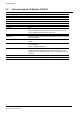
Technical data 5.2 Technical data for IP-Module CVVA-IP Electrical supply Power requirement Operating temperature range Storage temperature range Dimensions (H x Ø) Weight Material IP rating System requirements Protocols Installation Network connection Image formats Image transmission Security Hardware 10 Siemens Building Technologies Fire Safety & Security Products 12 V DC/24 V AC max. 6.0 W -10 – +50 °C, max. relative humidity 90% -20 – +60 °C, max.
Installing the IP-Module 6 Installing the IP-Module 6.1 Installing IP-Module type CFVA-IP Fig. 1 Exploded view of IP-Module CFVA-IP IP-Module fixing 1. Use the drilling template to drill two holes in the ceiling/wall and insert the wall plugs. 2. Mount the IP-Module to the ceiling/wall. 3. Connect the BNC cable (12) to the connector socket (4) in the IP-Module. Installation and connection of the dome camera 4. Connect the video output from the dome camera to the BNC cable video input (11). 5.
Installing the IP-Module 7. Place the camera body on the IP-Module and screw both units together using the two screws supplied. 8. Connect the LAN cable to the RJ45 socket (7). 9. Connect the (12 V DC / 24 V AC) electrical supply (8). WARNING Ensure correct polarity if using a 12 V DC supply, as incorrect connection may damage the dome camera or cause the unit to operate abnormally. 10.Establish communication with the device for the first time.
Installing the IP-Module IP-Module fixing The IP-Module features two apertures through which you can feed the cables: An aperture in the base An aperture in the side If you wish to use the side aperture: – Loosen the fixing screw (9) inside the IP-Module. – Remove the blanking screw from the side cable aperture and screw this into the cable aperture in the base of the unit. 1. Use the drilling template to drill two holes in the ceiling/wall and insert the wall plugs. 2.
Establishing initial communication with the device 7 Establishing initial communication with the device The factory settings for the IP address and subnet mask are 192.168.100.100 and 0.0.0.0 respectively. Communication between the device and the client PC is only possible if both the client PC and the device are located in the same network segment. There are two possible methods of achieving this: Changing the IP address of the client PC. See section 7.1: Changing the IP address of the client PC.
Establishing initial communication with the device The client PC IP address is now displayed. In this example, we have assumed IP address 10.11.12.13. 3. Type route add 192.168.100.0 mask 255.255.255.0 10.11.12.13 and press the Enter key. The ensuing network route ensures device accessibility. Note that you should enter your own client PC IP address instead of 10.11.12.13. 4. Check that there is communication with the device by typing ping 192.168.100.100. 5.
Checking device accessibility 8 Checking device accessibility Your device is accessed in the network via its IP address. The IP address is either preset at the factory (IP address 192.168.100.100) or set by you when allocating a new IP address to your device. See section 10.1: Changing the device IP address. 1. Type the following command in the your client PC's command prompt screen: 2. ping xxx.xxx.xxx.xxx xxx.xxx.xxx.xxx = 192.168.100.100 if the IP address set by the factory is used xxx.xxx.xxx.
Device homepage 9 Device homepage 9.1 Calling up the device homepage There are two ways of calling up the device homepage: Using Internet Explorer Using the Web-Cam IP Manager 9.1.1 Calling up the device homepage using Microsoft Internet Explorer 1. Type the IP address that is allocated to the device in the http address line in Internet Explorer. See section 10.1: Changing the device IP address. e. g.: http://141.73.31.3/ 2. Press the Enter key. The device homepage will be displayed. 9.1.
Device homepage 2. Click on the Start button. The Web-Cam IP Manager program window will now display a list of all the devices available for communication along with their IP addresses and MAC addresses. Each device's IP address or MAC address is unique. 3. Select the device whose homepage you want to call up. 4. Click on the Home page of selected device... button The homepage of the selected device is now called up. See section 9.2: Components of the device homepage.
Device homepage 9.2 Components of the device homepage Fig. 3 1 2 3 4 5 Device homepage Buttons for displaying live video images. See section 15.1: Displaying live video Submenu Language selection list box. Standard setting: English Main menus Display area for live video images. See section 15.
Configuring network settings 10 Configuring network settings 1. Call up the device homepage. See section 9.1: Calling up the device homepage. 2. Select Network settings in the Configuration menu. The Network settings dialogue window opens: Fig. 4 Network settings 3. Enter the desired settings in this dialogue window. 4. The settings are described in detail below. 5. Click on Save. 6. Restart your IP-Module. See section 14: Restarting the IP Module. The network settings will be adopted.
Configuring network settings Gateway (Next Hop) MAC-Address Link Speed 10.1 Enter the gateway IP address in this box. The gateway is the computer in the network, which establishes the connection between different network segments. If the device is only to be accessed by other devices in the same network segment, enter 0.0.0.0 here. Displays the network card ID. Choose the speed from the list. Automatic is the preferred setting.
Configuring network settings Like the IP address, the subnet mask also consists of four numbers in the range 0 – 255, all separated from each other by decimal points. The subnet mask tells the device which other IP addresses in the connected network (subnet) can be dialed directly and which addresses have to be dialed through the gateway.
Configuring network settings Each device's IP address or MAC address is unique. 3. Select the device whose IP address you want to change. 4. Click on the Set IP Address button. The following dialogue window opens: 5. Either manually enter the desired IP address, subnet mask and gateway (if required), or activate the check box if you want the DHCP server to determine these parameters. The settings will be adopted immediately. This process takes about 40 seconds.
Configuring image parameters 11 Configuring image parameters 11.1 Configuring general image parameters 1. Call up the device homepage. See section 9.1: Calling up the device homepage. 2. Select Image parameters in the Configuration menu. The Image parameters dialogue window opens: 3. Enter the desired settings in this dialogue window.
Configuring image parameters Overlay text Overlay text position Overlay text color 11.3 You can select the parameters that are to be overlaid on the live video image here. The following options are available: – (no text overlay) Time Time and date Video source Video source and time Video source + time + date You can select the position of the text overlay on the live video image here.
Configuring image parameters 3. Enter the desired settings in this dialogue window. 4. Select the quality level for each resolution from the options in the Quality list box. 5. We recommend you to set the quality level to Medium. 6. Select the font size for the text overlay from the options in the Diplay Font Size list box: The following options are available: – (no text overlay) Small Large 7. Select the input signal from the options in the Video Standard list box.
Setting the date and time 12 Setting the date and time 1. Call up the device homepage. See section 9.1: Calling up the device homepage. 2. Select Date and Time in the Configuration menu. The Date and Time dialogue window opens: Fig. 5 Date and time The time and date that were current when the device start page was loaded appear in the relevant boxes. You can set the device's built-in real-time clock here. 3. Choose the desired settings from the list of options for each field. 4. Click on Save.
Configuring user names and passwords 13 Configuring user names and passwords You can define user names and passwords for device configuration and image access (live image access rights). Factory set user names For configuration: – User name: config For image access: – User name: image 1. Call up the device homepage. See section 9.1: Calling up the device homepage. 2. Select Security in the Configuration menu. The Security dialogue window opens: Fig. 6 Security 3. Enter the desired user name (max.
Restarting the IP Module 14 Restarting the IP Module Certain settings changes (e.g. network settings) will only come into effect after a device restart. 1. Call up the device homepage. See section 9.1: Calling up the device homepage. 2. Select Restart in the Configuration menu. The Restart dialogue window opens: Fig. 7 Restart There are three ways of performing a restart: Manual restart Time controlled restart Restart by Ping Watchdog Manual restart 1. Click on the Restart now button.
Restarting the IP Module Restart by Ping Watchdog The watchdog is not active when the camera transmits a video stream. 1. Activate the Enable restart by Ping-Watchdog check box. 2. Enter the IP-Address of the Gateway (Next Hop) in the Remote Host to Ping box. See Fig. 4: Network settings. 3. Enter the desired cycle time in seconds in the Frequency box, e. g. 30. The device will ping the Remote Host to Ping you have entered every 30 seconds. 4. Enter the desired cycle time in seconds in the Timeout box, e.
Live video 15 Live video 15.1 Displaying live video The data stream consists of individual JPEG-coded images, separated from each other by markers (boundaries). The software automatically selects the best possible live video display modus for the browser that is used: Netscape and Mozilla support multipart JPEG. In this case, the live images are displayed directly without the use of an extra plug-in.
Live video 1 2 3 4 5 6 15.2 Resolution submenu Text overlay. See section 11.2: Configuring text overlay. Display area for live video Status. Playing Pause Pause button Switches from live video display to still picture display Display live video button Switches from still picture display to live video display Setting live video resolution Select the size of the live video display window in the Resolution submenu (as a function of the selected image quality).
Establishing access to the device via internet 16 Establishing access to the device via internet If it is necessary to be able to access your device via Internet, you must ensure that your IP address is internet-enabled. An Internet Service Provider (ISP) can supply you with an internet-enabled IP address. The ISP will offer you static or dynamic IP addresses. Connecting to internet Fig. 8 Connecting to internet Static IP address The ISP will supply you with an IP address once only.
Establishing access to the device via internet connection is interrupted, the newly allocated IP address must be assigned to your domain name, e.g. , so that your device can still be accessed using your domain name. Example of access using a dynamic IP address Requirements: Your device is part of a local network (LAN) and is connected to internet by a ROUTER, e.g. a TDSL router. An ISP (Internet Service Provider) has already allocated you an IP address.
Embedding live video images in a dedicated HTML page 17 Embedding live video images in a dedicated HTML page Embedding live video images Live video images cannot be embedded using Microsoft Internet Explorer! The live video images delivered by the device can be embedded in dedicated HTML pages using the following HTML tag, e. g.:  PAGE 36
Service mode 18 Service mode The service mode allows the device IP address to be reset even if the IP address that is currently allocated to the device is not known. If, for example, the Automatic Network Configuration (DHCP) option is activated when communication with the device is first established, the device will automatically be allocated an IP address by the DHCP server following each restart. This address is not known prior to the event and can change each time a restart takes place.
Index 19 Index A J Accessibility Checking device accessibility, 16 JPEG encoder settings Configuring JPEG encoder settings, 25 B L Brightness Configuring brightness, 24 Live video Displaying live video, 31 Live video images Embedding live video images in a dedicated HTML page, 35 C Contrast Configuring contrast, 24 D Declaration of conformity, 8 Device homepage Calling up the device homepage, 17 Components of the device homepage, 19 E EMC Directive, 8 EU Directive, 8 Exploded view IP-Module Exp
Herausgegeben von Siemens Building Technologies Fire & Security Products GmbH & Co. oHG D-76181 Karlsruhe www.sbt.siemens.com Dokument Nr. A24205-A336-B383 Ausgabe 07.2005 © Copyright by Siemens Building Technologies AG Liefermöglichkeiten und technische Änderungen vorbehalten. Gedruckt in der Bundesrepublik Deutschland auf umweltfreundlich chlorfrei gebleichtem Papier.