
Installation guide
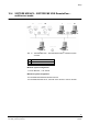
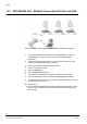


USB input/output modules
94
Siemens Building Technologies
Fire Safety & Security Products 08.2007
11.3 Module addressing
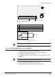
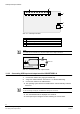
11.3.1 Modules with 8 inputs/outputs
Addressing is done using the module address.
1. Assign the module addresses using the jumpers. See Section 11.2:
Connecting USB input/output modules.
Module address 0
Module address 1
Module address 2
Module address 3
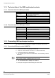
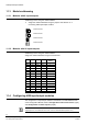
11.3.2 Modules with 16 inputs/outputs
Addressing is done using the module address.
Assign the module addresses using the DIP switches.
SW1 SW2 SW3 SW4 Module
address
On On On On 0
Off On On On 1
On Off On On 2
Off Off On On 3
On On Off On 4
Off On Off On 5
On Off Off On 6
Off Off Off On 7
On On On Off 8
Off On On Off 9
On Off On Off 10
Off Off On Off 11
On On Off Off 12
Off On Off Off 13
On Off Off Off 14
Off Off Off Off 15
11.4 Configuring USB input/output modules
The configuration of input/output modules is described in the SISTORE MX NVS
V2.60 Configuration Manual, Section Configuration of the alarm sensors (input)
and Configuration of switch outputs (output).
NOTE
Digital inputs are not available with the current version of SISTORE MX NVS (March 2007).