
Installation guide


USB input/output modules
93
Siemens Building Technologies
Fire Safety & Security Products 08.2007
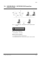
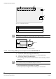
Abb. 20 USB input and output module
1, 2 Relay/optocoupler outputs
3 0 V
4 12 V
5 JP1 power supply USB/external
6 USB port
7 DIP1
8, 9 Optocoupler input
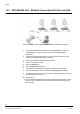
NOTE
Connect the input cables (+/-) as printed on the input/output module. The output cables can be
connected in any way as the outputs are no-voltage connections.
Make sure that jumper JP1 is plugged onto pins 2 and 3 (USB).
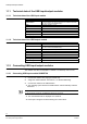
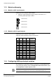
USB Input Module
5 ... 30V
Abb. 21 Connection of USB input module
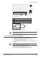
USB Output Module
max. 30V
Abb. 22 Connection of USB output module
+
-