
Installation guide


USB input/output modules
90
Siemens Building Technologies
Fire Safety & Security Products 08.2007
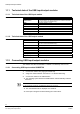
11.1 Technical data of the USB input/output modules
11.1.1 Technical data of the USB input module
System bus USB
Module address can be set between 0-3 using jumpers (up to 4 modules of the same
type can be connected simultaneously)
Inputs 8, optically isolated (5 – 30 V)
Input current max. 10 mA
LEDs initialization, status of input signals
Connections pluggable screw terminals
CE yes
Operating temperature 0 to 70 °C
Power supply via USB
11.1.2 Technical data of the USB output module
System bus USB
Module address can be set between 0-3 using jumpers (up to 4 modules of the same
type can be connected simultaneously)
Outputs 8 DIL relays (max. 15 W/1 A)
Switchable voltage 30 V
LEDs initialization, status of relays
Connections pluggable screw terminals
CE yes
Operating temperature 0 to 70 °C
Relay switching time 1 ms (incl. bounce)
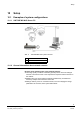
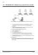
11.2 Connecting USB input/output modules
The modules can either be installed in a cabinet or as desk-top units on a PC.
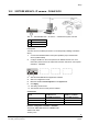
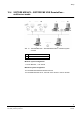
11.2.1 Connecting USB input module USBOPT08
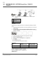
1. Connect the module via a plug-type terminal strip.
2. Assign the module address. See Section 11.3: Module addressing.
3. Connect the module to the USB interface.
Î The operating system detects the USB modules and automatically activates
the drivers.
NOTE
In case a message is displayed, click OK until all dialog boxes are closed.
Î The new hardware will be displayed as a QuickInfo.
Î Each input is assigned an LED indicating the current status.