SISTORE MX NVS Anwendungssoftware für netzwerkbasierende Videoaufzeichnung Installationsanleitung (DE) Installation Guide (EN) Ab Softwareversion V2.
Liefermöglichkeiten und technische Änderungen vorbehalten. Data and design subject to change without notice. / Supply subject to availability. © 2007 Copyright by Siemens Building Technologies Wir behalten uns alle Rechte an diesem Dokument und an dem in ihm dargestellten Gegenstand vor.
Inhalt 1 1.1 1.2 1.2.1 1.2.2 1.2.3 1.2.4 Sicherheit.................................................................................................5 Zielgruppen ...............................................................................................5 Allgemeine Sicherheitshinweise ...............................................................5 Handhabung..............................................................................................5 Transport.........................................
Sicherheit 10 10.1 10.1.1 10.1.2 10.2 10.3 10.4 10.5 Inbetriebnahme .....................................................................................35 Beispiele für Systemaufbau ....................................................................35 SISTORE MX NVS Server PC ................................................................35 Allgemeines zu Netzwerkkameras..........................................................35 SISTORE MX NVS – IP-Kamera – CKA4810 / 20.................................
Sicherheit 1 Sicherheit 1.1 Zielgruppen Die Anweisungen in diesem Dokument richten sich nur an die folgende/n Zielgruppe/n: 1.2 Zielgruppe Qualifikation Tätigkeit Installateur Besitzt eine zur Installiert Software zum Installation und zum Gerät. Produkt passende Fachausbildung und eine Schulung zum Produkt. Gerätezustand Erstmalig in Betrieb genommenes, fertig montiertes oder umgebautes Gerät.
Sicherheit 1.2.3 Aufbewahrung Produktschaden durch falsche Lagerung – Bewahren Sie die CD nur in einer CD-Hülle auf. – Bewahren Sie die CD bei einer Luftfeuchtigkeit von 10 – 90 % auf. – Bewahren Sie die CD bei einer Umgebungstemperatur von -5 – +55 °C auf. – Bewahren Sie die CD nicht an extrem staubigen Orten auf. – Bewahren Sie die CD nicht in der Nähe einer magnetischen Strahlungsquelle auf. – Schützen Sie die CD vor Nässe. – Schützen Sie die CD vor direkter Sonneneinstrahlung. 1.2.
Lieferumfang 2 Lieferumfang z USB-Dongle für die Softwarelizenz mit 4, 9, 16 oder 32 Netzwerk-Kameras Dongle 4 Betrieb mit 4 Netzwerk-Kameras Dongle 9 Betrieb mit 9 Netzwerk-Kameras Dongle 16 Betrieb mit 16 Netzwerk-Kameras Dongle 32 Betrieb mit 32 Netzwerk-Kameras HINWEIS Ohne USB-Dongle befindet sich die Software im Demo-Betrieb. Im Demo-Betrieb können Sie nur eine Netzwerk-Kamera anlegen, parametrieren und auswerten.
Systemvoraussetzungen 4 Systemvoraussetzungen z Pentium IV mindestens 2,6 GHz z Mind. 512 MB RAM, empfohlen: 1024 MB z Grafikkarte S-VGA 1024 x 768, 16 Bit Farbtiefe, 64 MB Grafikspeicher oder mehr z Der Grafikkartentreiber muss die Funktionalität von Direct Draw ab V8.x komplett unterstützen z Festplatte 120 GB oder mehr z Systempartition mind. 10 GB, empfohlen: 20 MB z CD-/DVD-Laufwerk / Brenner z MF2-Tastatur, Maus z Netzwerkanschluss z Mind. 2 x USB-Ansschluss (2.
Softwarekomponenten 5 Softwarekomponenten Bei der Installation des SISTORE MX NVS können Sie die folgenden Softwarekomponenten installieren: z SISTORE MX NVS Applikationsprogramm z Hardware-Treiber nachinstallieren z RemoteView (Client) 5.1 Netzwerk-Kameras Die Softwarekomponente Netzwerk-Kameras ermöglicht es über einen PC bis zu 32 Netzwerk-Kameras und USB Ein- und Ausgangsmodule zu konfigurieren.
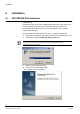
Installation 6 Installation 6.1 SISTORE MX NVS installieren Voraussetzung: Der Benutzer (user) ist mit mind. Hauptbenutzerrechten (main user), besser noch mit Administratorrechten (admin user) angemeldet. Das gilt sowohl für die Neuinstallation der Software als auch für ein nachträgliches Treiber-Update. Systemvoraussetzungen: Die Systemvoraussetzungen finden Sie in Kap. 4: Systemvoraussetzungen. 1. Legen Sie die mitgelieferte CD in das entsprechende Laufwerk Ihres PCs ein. 2.
Installation 5. Î Klicken Sie auf die Schaltfläche Weiter. Folgendes Dialogfenster wird geöffnet: 6. Wählen Sie einen Zielordner aus. 7. Klicken Sie auf die Schaltfläche Weiter. Î 8. Folgendes Dialogfenster wird geöffnet: Wählen Sie die gewünschte Softwarekomponente (vgl. Kap. 5 Softwarekomponenten). HINWEIS Informationen zur benutzerspezifischen Installation finden Sie in Kapitel 6.2 „Hardware-Treiber nachinstallieren“. 9. Î Klicken Sie auf die Schaltfläche Weiter.
Installation 10. Geben Sie hier den Name des Programmordners ein und klicken Sie auf die Schaltfläche Weiter. Î Folgendes Fenster wird geöffnet: 11. Schließen Sie alle laufenden Programme und klicken Sie die Schaltfläche OK. Î Nun werden die gewünschten Komponenten installiert. 12. Klicken Sie auf die Schaltfläche Weiter. Î Folgendes Fenster wird geöffnet: 13. Bestätigen Sie mit Ja. Î Folgendes Dialogfenster wird geöffnet: 12 Siemens Building Technologies Fire Safety & Security Products 08.
Installation 14. Klicken Sie auf die Schaltfläche Fertig stellen. Î Der Computer wird neu gestartet. 15. Schließen Sie nach dem Neustart des PCs einen USB-Dongle an den USB-Anschluss ihres PCs an. Vergleichen Sie hierzu Kap. 2: Lieferumfang. 16. Leisten Sie den Anweisungen des Dongle-Treibers Folge, bis der DongleTreiber korrekt installiert ist. 17. Starten Sie SISTORE MX NVS neu. 13 Siemens Building Technologies Fire Safety & Security Products 08.
Installation 6.2 Hardware-Treiber nachinstallieren Voraussetzung: Der Benutzer (user) ist mit mind. Hauptbenutzerrechten (main user), besser noch mit Administratorrechten (admin user) angemeldet. Das gilt sowohl für die Neuinstallation der Software als auch für ein nachträgliches Treiber-Update. Systemvoraussetzungen: Die Systemvoraussetzungen finden Sie in Kap. 4: Systemvoraussetzungen. 1. Legen Sie die mitgelieferte CD in das entsprechende Laufwerk Ihres PCs ein. 2.
Installation Hardware-Treiber Funktion CKA4810/CKA4820 Ansteuerung eines CKA-Bedienpultes Hardware Watchdog Ansteuerung einer zusätzlichen Baugruppe im PC (Typ PWDOG1 der Firma Quancom) 5. Wählen Sie die CKA4810 / CKA4820 oder Hardware Watchdog. 6. Klicken Sie auf die Schaltfläche Weiter. Î 7. Folgendes Dialogfenster wird geöffnet: Klicken Sie auf die Schaltfläche Fertig stellen. Î Der Computer wird neu gestartet.
Installation 6.3 RemoteView auf Client-PC installieren Voraussetzung: Der Benutzer (user) ist mit mind. Hauptbenutzerrechten (main user), besser noch mit Administratorrechten (admin user) angemeldet. Das gilt sowohl für die Neuinstallation der Software als auch für ein nachträgliches Update. 1. Benutzen Sie ein CD-Laufwerk oder kopieren Sie die mitgelieferte Software auf einen Memory-Stick. 2. Starten Sie die Datei SISTORE_MX_ RemoteView_260_SP1.exe vom genannten Datenträger.
Installation 5. Î Klicken Sie auf die Schaltfläche Weiter. Folgendes Dialogfenster wird geöffnet: Abb. 3 Zielordner auswählen 6. Behalten Sie den vorgeschlagenen Zielordner bei. 7. Klicken Sie auf die Schaltfläche Weiter. Î Folgendes Dialogfenster wird geöffnet: Abb. 4 Setup-Typ wählen 8. Wählen Sie den Setup-Typ RemoteView. 9. Klicken Sie auf die Schaltfläche Weiter. 17 Siemens Building Technologies Fire Safety & Security Products 08.
Installation Î Folgendes Dialogfenster wird geöffnet: Abb. 5 Programmordner wählen 10. Behalten Sie den vorgeschlagenen Programmordner SISTORE MX REMOTEVIEW bei. 11. Klicken Sie auf die Schaltfläche Weiter. Î Folgendes Fenster wird geöffnet: 12. Schließen Sie alle laufenden Programme und klicken Sie die Schaltfläche OK. Î Die Installation wird durchgeführt.
Installation Abb. 6 Installation abgeschlossen 13. Klicken Sie auf die Schaltfläche Fertig stellen. Î Das Programm SistoreMX RemoteView ist installiert. 19 Siemens Building Technologies Fire Safety & Security Products 08.
Installation 6.4 SISTORE MX NVS entfernen 1. Starten Sie die Datei SISTORE_MX_NVS_260_SP1.exe Î Folgendes Fenster wird geöffnet: 1. Markieren Sie die Auswahl Programm entfernen. 2. Klicken Sie auf Weiter Î Sie gelangen automatisch ans Programmende. HINWEIS Falls das CEVIS bzw. Siemens-Verzeichnis nach der Deinstallation noch vorhanden ist, müssen Sie es manuell löschen. 6.5 Software-Update von SISTORE MX NVS und RemoteView 6.5.1 Version 2.5x auf 2.
Konfiguration 7 Konfiguration 7.1 Software aufrufen 1. Doppelklicken Sie auf dem Desktop die Verknüpfung SISTORE MX NVS. ODER 1. Wählen Sie im Startmenü von Windows das Verzeichnis SISTORE MX NVS. HINWEIS Bei Stoppen einer ereignisgesteuerter Aufnahme wird der aktuelle Voralarmring gelöscht! 21 Siemens Building Technologies Fire Safety & Security Products 08.
Konfiguration 7.2 In das System einloggen 1. Wählen Sie aus dem Menü Datei den Menüpunkt Login. 2. klicken Sie auf die Schaltfläche Login Î 3. in der Symbolleiste. Es wird folgender Login-Dialog geöffnet: Machen Sie im Login-Dialog folgende Eingaben: Benutzername Geben Sie hier den für Sie vom Administrator angelegten Benutzernamen ein. Beachten Sie dabei Groß- und Kleinschreibung. Passwort Geben Sie hier das für Sie vom Administrator angelegte Kennwort ein.
Konfiguration 7.4 Passwort ändern Sie haben zwei Möglichkeiten das Passwort zu ändern: z Über den Menüpunkt Neues Passwort z Über den Menüpunkt Benutzerverwaltung 7.4.1 Passwort ändern über den Menüpunkt Neues Passwort 1. Wählen Sie im Menü Datei den Menüpunkt Neues Passwort. 2. Geben Sie das existierende Passwort in das Eingabefeld Altes Passwort ein. 3. Geben Sie Ihr neues Passwort in Neues Passwort und Wiederholung ein. HINWEIS Die minimale Passwortlänge beträgt acht Zeichen. 4. 7.4.
Konfiguration 7.5 Sprachversion ändern 1. Î Wählen Sie aus dem Menü Verwaltung den Menüpunkt Konfiguration. Das Dialogfenster Konfiguration wird geöffnet. 2. Klicken Sie auf das Register System. 3. Legen Sie die Sprachversion fest, mit der SISTORE MX NVS arbeiten soll. Î SISTORE MX NVS sucht alle installierten Sprachen und listet diese in einer Combobox auf. Es können jederzeit weitere Sprachen installiert werden.
Konfiguration 7.6 Sprachversion unter Windows XP ändern 1. Wählen Sie Start -> Einstellungen -> Systemsteuerung -> Regions- und Sprachoptionen. 2. Wählen Sie das Register Regionale Einstellungen. Î 3. Folgendes Dialogfenster wird geöffnet: Nehmen Sie im Register folgende Einstellungen vor: Standards und Formate Deutsch (Deutschland) Standort Deutschland 4. Klicken Sie auf die Schaltfläche Übernehmen. 5. Wählen Sie das Register Sprachen.
Konfiguration Î 6. Î 7. Folgendes Dialogfenster wird geöffnet: Klicken Sie auf die Schaltfläche Details. Folgendes Dialogfenster wird geöffnet: Nehmen Sie im Register Einstellungen folgende Einstellungen vor: Standard-Eingabegebietsschema Deutsch (Deutschland) - Deutsch 8. Klicken Sie auf die Schaltfläche Übernehmen. 9. Klicken Sie auf die Schaltfläche OK. 26 Siemens Building Technologies Fire Safety & Security Products 08.
Konfiguration Î Das Dialogfenster Regions- und Sprachoptionen öffnet sich: 10. Nehmen Sie im Register Erweitert folgende Einstellungen vor: Sprache für Programme, die Unicode nicht unterstützen Deutsch (Deutschland) 11. Klicken Sie auf die Schaltfläche Übernehmen. 12. Klicken Sie auf die Schaltfläche OK. Î Das System wird neu gebootet. 27 Siemens Building Technologies Fire Safety & Security Products 08.
Konfiguration 7.7 Datum und Uhrzeit auf deutsches Format stellen 1. Stellen Sie nach den Spracheinstellungen zur Software ggf. Datum und Uhrzeit auf das deutsche Format. 2. Wählen Sie Start -> Einstellungen -> Systemsteuerung -> Regions- und Sprachoptionen. 3. Klicken Sie auf die Schaltfläche Anpassen. 4. Wählen Sie das Register Uhrzeit. Î Folgendes Dialogfenster wird geöffnet: 5. Wählen Sie das gewünschte Zeitformat. 6. Klicken Sie auf die Schaltfläche Übernehmen.
Konfiguration 7. Î Wechseln Sie das Register Datum. Folgendes Dialogfenster wird geöffnet: 8. Wählen Sie das gewünschte Datumsformat. 9. Klicken Sie auf die Schaltfläche Übernehmen. 10. Klicken Sie auf die Schaltfläche OK. 29 Siemens Building Technologies Fire Safety & Security Products 08.
Konfiguration 7.8 Auflösung und Dateiformat Die von SISTORE MX NVS erstellten Bilddateien haben die Endung .K26 oder .avi – je nach Parametrierung. Diese wird im Register Konfiguration-System im Feld Aufnahme eingestellt. Bei den Dateien mit der Endung .k26 handelt es sich um verschlüsselte Bilddateien in einem AVI-ähnlichen Format, die nur mit dem SISTORE Player ausgewertet werden können.
Konfiguration 7.9 Zeitzone und Uhrzeit des PCs einstellen Stellen Sie die Uhrzeit Ihres PCs gemäß der entsprechenden Zeitzone (z. B. GMT + 01:00 Amsterdam, Berlin, Bern, Rome, Stockholm, Vienna) ein. Diese Einstellung können Sie im Windows Startmenü unter Start > Einstellungen > Systemsteuerung > Datum/ Uhrzeit vornehmen: Abb. 8 Datum/Uhrzeit über das Start Menü verändern 31 Siemens Building Technologies Fire Safety & Security Products 08.
Konfiguration 7.10 Zeit des Client PCs von NTP-Server holen Ein NTP-Server liefert immer die aktuelle Zeit. Die Zeit Ihres PCs wird dabei ständig mit der Zeit des NTP-Servers aktualisiert. Dies ist eine zyklische Synchronisationsart, d. h. die Zeit wird in regelmäßigen Abständen aktualisiert. Um die Zeit Ihres PCs von einem NTP-Server zu holen, muss die IP-Adresse des NTPServers angegeben werden. 1. Öffnen Sie dazu die Eingabeaufforderung Ihres Client PCs über das Windows Start Menü. Abb. 9 2.
Konfiguration 7.11 Weitere Informationen Ausführliche Informationen zur Software SISTORE MX NVS V2.60 (und dem vorliegenden WebView) finden Sie in der Onlinehilfe oder in den entsprechenden Dokumenten auf der Software-CD. 33 Siemens Building Technologies Fire Safety & Security Products 08.
Software aktualisieren 8 Software aktualisieren Sollte es zu einem späteren Zeitpunkt notwendig sein, die SISTORE MX NVS Software zu reparieren oder neu zu installieren, 1. Gehen Sie bitte wie in Kap. 6.2 „Hardware-Treiber nachinstallieren“ beschrieben vor. 2. Wählen Sie die Option Software aktualisieren (Update). Î 9 Diese bewirkt, dass alles, was bei der letzten Installation installiert wurde, nochmals installiert wird.
Inbetriebnahme 10 Inbetriebnahme 10.1 Beispiele für Systemaufbau 10.1.1 SISTORE MX NVS Server PC Abb. 11 Systemübersicht SISTORE MX NVS 1 Max. 32 IP-Kameras oder IP-Dome 2 MX NVS Server PC 3 CKA4810/20 (optional) 10.1.2 Allgemeines zu Netzwerkkameras Beachten Sie Folgendes beim Einsatz von Netzwerkkameras: z Die Bildqualität von Netzwerkkameras ist generell schlechter als die von Analogkameras. Ursache ist die nötige Kompression, um das Netzwerk weniger zu belasten.
Inbetriebnahme SISTORE MX NVS unterstützt folgende Netzwerkkameras: Arecont Vision 2100, Vision 3130 Day, Vision 3130 Night Axis 205, 206/W, 206M, 210, 211, 212 PTZ, 213 PTZ, 216FD, 221, 223M, 231D+, 232D+, 240Q, 241Q, 241S, Generic HTTP Interface V1.0, Generic HTTP Interface V2.
Inbetriebnahme 10.2 SISTORE MX NVS – IP-Kamera – CKA4810 / 20 Abb. 12 1 Systemübersicht SISTORE MX NVS – IP Kamera –– CKA4810/20 CKA4810/20 2 MX NVS Server 3 Max. 32 IP-Kameras Voraussetzung: Der CKA-Treiber ist installiert (siehe Kap. 6.2 „Hardware-Treiber nachinstallieren“). 1. Schließen Sie das Bedienpult CKA4810 / 4820 (Anschluss COM1A) an den MX NVS-Server (COM1/COM2) an. 2. Parametrieren Sie den COM1A-Anschluss am Bedienpult für die Nutzung als RS232-Schnittstelle.
Inbetriebnahme 10.3 SISTORE MX NVS – SISTORE RemoteView – CKA4810 / CKA4820 Abb. 13 Systemübersicht SISTORE MX NVS – SISTORE RemoteView – CKA4810 1 CKA4810/20 2 Client PC mit RemoteView 3 MX NVS Server 4 Max. 32 IP-Kameras Voraussetzung: Der CKA-Treiber ist installiert (siehe Kap. 6.2 „Hardware-Treiber nachinstallieren“). 1. Schließen Sie das Bedienpult CKA4810 / CKA4820 (Anschluss COM1A) an den Client PC (COM1/COM2) an. 2.
Inbetriebnahme 10.4 SISTORE MX NVS – SISTORE MX NVS RemoteView – Multiserver Betrieb Abb. 14 Systemübersicht SISTORE MX NVS – SISTORE RemoteView – CKA4810 1 1 … max. 32 IP-Kameras / IP-Dome 2 1 … max. 16 Client PC 3 1 … max. 10 MX NVS Server Minimale Anlagengröße 1 x Server MX NVS, 1 x IP-Kamera Maximale Anlagengröße 16 x SISTORE MX NVS RemoteView Client PC 10 x SISTORE MX NVS Server mit je 32 IP-Kameras = 320 IP-Kameras 39 Siemens Building Technologies Fire Safety & Security Products 08.
Inbetriebnahme 10.5 SISTORE MX NVS – MX Multi Channel Box RCI 0601 und GAA Abb. 15 Systemübersicht – MX NVS Multi-Channel Box RCI 0601 und GAA 1. Schließen Sie die MX Multi-Channel Box an den SISTORE MX NVS Server PC (COM1/COM2) an. Hierzu benötigen Sie den Konverter 485SD9R (FA B&B Electronics). 2. Schließen Sie die GAA an das RCI0601 an. Informationen hierzu finden Sie im Benutzerhandbuch MX Multi-Channel Box RCI 0601. 3. Starten Sie die Software SISTORE MX NVS. 4.
USB Ein-/Ausgangsmodule 11 USB Ein-/Ausgangsmodule Die USB Ein-/Ausgangsmodule können Sie als Zubehör bestellen. Vergleichen Sie hierzu Kap. „Bestellangaben“ im SISTORE MX NVS Benutzerhandbuch. HINWEIS Sie benötigen keine zusätzlichen Netzteile. Die Spannungsversorgung erfolgt über eine USBSchnittstelle. USB Ein-/Ausgangsmodule z USBOPT08 (Eingangsmodul) z USBREL8 (Ausgangsmodul) z USBOPTOREL16 (Ein- und Ausgangsmodul) USBOPT08 USBREL8 Sie können bis zu vier Module des gleichen Typs anschließen.
USB Ein-/Ausgangsmodule 11.1 Technische Daten USB Ein-/Ausgangsmodule 11.1.1 Technische Daten USB Eingangsmodul 11.1.2 11.2 Systembus USB Moduladresse Über Steckbrücken einstellbar von 0-3 (Betrieb von bis zu 4 Modulen des gleichen Typs möglich) Eingänge 8, optisch getrennt (5 – 30 V) Eingangsstrom max.
USB Ein-/Ausgangsmodule 1 2 3 + – + – + – + – + – + – + – + – 5 Abb. 16 4 USB Eingangsmodul 1 Module Addressing 2 Configuration Status LED 3 USB-Schnittstelle 4 Input Status LED 5 Inputs + 5 ... 30V USB Input Module Abb. 17 - Anschluss USB Eingangsmodul HINWEIS Der Anschluss der Kabel (+/-) ist gemäß der Abb.15 vorzunehmen. 11.2.2 USB Ausgangsmodul USBREL8 anschließen 1. Schließen Sie das Modul über steckbare Klemmleisten an. 2. Weisen Sie dem Modul die Moduladresse zu.
USB Ein-/Ausgangsmodule 2 1 3 4 5 Abb. 18 USB Ausgangsmodul 1 Relay Outputs 2 Output Status LED 3 Module Addressing 4 Configuration Status LED 5 USB-Schnittstelle HINWEIS Der Anschluss der Kabel ist ohne Bedeutung, da dies potentialfreie Anschlüsse sind. max. 30V USB Output Module Abb. 19 Anschluss USB Ausgangsmodul 11.2.3 USB Ein- und Ausgangsmodul USBOPTOREL16 anschließen 1. Schließen Sie das Modul über steckbare Klemmleisten an. 2. Weisen Sie dem Modul die Moduladresse zu.
USB Ein-/Ausgangsmodule Abb. 20 USB Ein- und Ausgangsmodul 1, 2 Relais/Opto-Outputs 3 0V 4 12 V 5 JP1 Stromversorgung USB/extern 6 USB-Schnittstelle 7 DIP1 8, 9 Opto-Input HINWEIS Der Anschluss der Eingangskabel (+/-) ist so aufzulegen, wie die Bedruckung auf dem Ein- und Ausgangsmodul es anzeigt. Der Anschluss der Ausgangskabel ist ohne Bedeutung, da diese potentialfreie Anschlüsse sind. Beachten Sie, dass der Jumper JP1 auf Pin 2 und 3 gesteckt ist (USB). + 5 ...
USB Ein-/Ausgangsmodule 11.3 Moduladresse zuweisen 11.3.1 Module mit 8 Ein- bzw. Ausgängen Die Module werden über die Moduladresse angesprochen. 1. Weisen Sie die Adresse der Module über die Steckbrücken zu. Vergleichen Sie hierzu Kap. 11.2: USB Ein-/Ausgangsmodule anschließen. Moduladresse 0 Moduladresse 1 Moduladresse 2 Moduladresse 3 11.3.2 Module mit 16 Ein- und Ausgängen Die Module werden über die Moduladresse angesprochen. Weisen Sie die Adresse der Module über die Schalter zu. 11.
Herausgegeben von Siemens Building Technologies Fire & Security Products GmbH & Co. oHG D-76181 Karlsruhe www.sbt.siemens.com Dokument Nr. A6V10072823 Ausgabe 08.2007 © 2007 Copyright by Siemens Building Technologies Liefermöglichkeiten und technische Änderungen vorbehalten. Gedruckt in der Bundesrepublik Deutschland auf umweltfreundlich chlorfrei gebleichtem Papier.
SISTORE MX NVS Application Software for Network-Based Video Recording Installation Guide (EN) Software version V2.
Liefermöglichkeiten und technische Änderungen vorbehalten. Data and design subject to change without notice. / Supply subject to availability. © 2007 Copyright by Siemens Building Technologies AG Wir behalten uns alle Rechte an diesem Dokument und an dem in ihm dargestellten Gegenstand vor.
Contents 1 1.1 1.2 1.2.1 1.2.2 1.2.3 1.2.4 Safety .....................................................................................................53 Target readers.........................................................................................53 Work safety information ..........................................................................53 Handling ..................................................................................................53 Transport...............................
Safety 10 10.1 10.1.1 10.1.2 10.2 10.3 10.4 10.5 Setup ......................................................................................................83 Examples of system configurations ........................................................83 SISTORE MX NVS Server PC ................................................................83 General information about network cameras ..........................................83 SISTORE MX NVS - IP camera - CKA4810/20 ......................................
Safety 1 Safety 1.1 Target readers The instructions in this document are designed only for the following target readers: 1.2 Target readers Qualification Activity Condition of the equipment Installer Has appropriate technical training with regard to the installation and the product and has completed the training courses for product specialists. Installs software on devices. New, readily assembled and installed device or modified device.
Safety 1.2.3 Storage Damage due to improper storage – Always store the CD in its protective case. – Keep the CD in an environment with a relative humidity of 10 – 90 %. – Keep the CD between -5 and +55 °C. – Do not store the CD in excessively dusty places. – Do not keep the CD close to sources of magnetic radiation. – Protect the CD from moisture. – Protect the CD from direct sunlight. 1.2.4 Service and maintenance Data loss after update – Make sure to backup all data before updating the system.
Scope of Delivery 2 Scope of Delivery z USB dongle for software licence with 4, 9, 16 or 32 network cameras Dongle 4 Operation of 4 network cameras Dongle 9 Operation of 9 network cameras Dongle 16 Operation of 16 network cameras Dongle 32 Operation of 32 network cameras NOTE If no USB dongle is installed, the software only runs in demo mode. In demo mode you can configure and evaluate only one network camera.
System requirements 4 System requirements z Pentium IV 2,6 GHz or higher z Min. 512 MB RAM, recommended: 1024 MB z S-VGA graphics card, 1024 x 768, 16-bit colour depth, graphics memory 64 MB or higher z The graphics card driver must fully support Direct Draw functionality V8.x or higher z Hard disk capacity 120 GB or higher z System partition min. 10 GB, recommended: 20 MB z CD/DVD drive / burner z MF2 keyboard, mouse z Network connection z Min. 2 USB ports (2.
Software components 5 Software components During the installation of the SISTORE MX NVS application you can install the following software components: z SISTORE MX NVS application program z Subsequently install hardware driver z RemoteView (client) 5.1 Network cameras This software component permits up to 32 network cameras and USB input/output modules to be configured via a PC. NOTE With SISTORE MX NVS it is not possible to record the video signals supplied by analogue cameras. 5.
Installation 6 Installation 6.1 Installing SISTORE MX NVS Prerequisite: To log into the system, the user must at least have main user or rather admin user rights. This applies to the first-time installation of the software as well as to a subsequent driver update. System requirements: For the system requirements please refer to Section 4: System requirements. 1. Place the CD in the appropriate drive of your PC. 2. Start SISTORE_MX_NVS_260_SP1.exe.
Installation 5. Î Click Next. The following dialog box will appear: 6. Select a destination folder. 7. Click Next. Î 8. The following dialog box will appear: Select the desired software component (see Section 5: Software components). NOTE For more detailed information on user-specific installation please refer to Section 6.2: Subsequently installing a hardware driver. 9. Î Click Next. The following dialog box will appear: 59 Siemens Building Technologies Fire Safety & Security Products 08.
Installation 10. Enter the name of the program folder and click Next. Î The following window will appear: 11. Close all programs and click OK. Î The desired components will now be installed. 12. Click Next. Î The following window will appear: 13. Confirm with Yes. Î The following dialog box will appear: 60 Siemens Building Technologies Fire Safety & Security Products 08.
Installation 14. Click Finish. Î The computer will be restarted. 15. After restarting your PC, connect a USB dongle to the USB port. See Section 2: Scope of Delivery. 16. Follow the instructions for the installation of the dongle driver until the dongle driver is installed correctly. 17. Restart SISTORE MX NVS. 61 Siemens Building Technologies Fire Safety & Security Products 08.
Installation 6.2 Subsequently installing a hardware driver Prerequisite: To log into the system, the user must at least have main user or rather admin user rights. This applies to the first-time installation of the software as well as to a subsequent driver update. System requirements: For the system requirements please refer to Section 4: System requirements. 1. Place the CD in the appropriate drive of your PC. 2. Start SISTORE_MX_NVS_260_SP1.exe.
Installation Hardware driver Function CKA4810 / CKA4820 Activation of a CKA control panel Hardware watchdog Activation of an additional module in the PC (type PWDOG1 from Quancom) 5. Select CKA4810 / CKA4820 or Hardware Watchdog. 6. Click Next. Î 7. Î Î The following dialog box will appear: Click Finish. The computer will be restarted. When the computer is restarted, the symbol for CKA will appear in the task bar. 1 8. CKA symbol Restart SISTORE MX NVS RemoteView.
Installation 6.3 Installing RemoteView on a client PC Prerequisite: To log into the system, the user must at least have main user or rather admin user rights. This applies to the first-time installation of the software as well as to a subsequent update. 1. You can either use a CD drive or copy the software supplied onto a memory stick. 2. Launch the file SISTORE_MX_ RemoteView_260_SP1.exe.
Installation 5. Î Click Next. The following dialog box will appear: Abb. 3 "Choose Destination Location" dialog 6. Do not change the destination folder. 7. Click Next. Î The following dialog box will appear: Abb. 4 "Setup type" dialog 8. Select the setup type RemoteView. 9. Click Next. 65 Siemens Building Technologies Fire Safety & Security Products 08.
Installation Î The following dialog box will appear: Abb. 5 "Select program folder" dialog 10. Do not change the SISTORE MX REMOTEVIEW program folder. 11. Click Next. Î The following window will appear: 12. Close all programs and click OK. Î The installation will now be carried out. Î Wait until the window InstallShield Wizard Complete appears: 66 Siemens Building Technologies Fire Safety & Security Products 08.
Installation Abb. 6 "InstallShield Wizard Complete" dialog 13. Click on Finish. Î SISTORE MX RemoteView is now installed. 67 Siemens Building Technologies Fire Safety & Security Products 08.
Installation 6.4 Removing SISTORE MX NVS 1. Start SISTORE_MX_NVS_260_SP1.exe. Î The following window will appear: 1. Select the option Remove. 2. Click Next. Î This automatically takes you to the end of the program. NOTE If the CEVIS or Siemens directory still exists after uninstalling the program, it has to be deleted manually. 6.5 Updating SISTORE MX NVS and RemoteView software 6.5.1 From version 2.5x to version 2.
Configuration 7 Configuration 7.1 Starting the software 1. Double-click on the desktop shortcut SISTORE MX NVS. or 1. Select the directory SISTORE MX NVS in the Windows start menu. NOTE If an event-triggered recording is stopped, the current pre-alarm ring storage will be cleared. 69 Siemens Building Technologies Fire Safety & Security Products 08.
Configuration 7.2 Login 1. Choose Login from the File menu. 2. Click on the Login button Î 3. in the toolbar. The following dialog box will appear: Enter the following in the login dialog: User name Enter the user name created for you by the administrator. The entry is casesensitive. Password Enter the password created for you by the administrator. The password is displayed as asterisks (***). The entry is case-sensitive.
Configuration 7.4 Change password There are two options for changing the password: z By selecting the menu item New password z By selecting the menu item User management 7.4.1 Changing the password using the menu item New password 1. Select New password in the File menu. 2. Enter the current password in the appropriate field for the Old password. 3. Enter the new password in the fields New password and Confirm password. NOTE The password should be at least eight characters long. 4. 7.4.
Configuration 7.5 Select language 1. Î Select Configuration in the Administration menu. The Configuration dialog box will appear. 2. Select the System tab. 3. Stipulate the language in which SISTORE MX NVS is to operate. Î SISTORE MX NVS finds all languages and lists them in a combo box. Further languages can be installed at any time. You can now select a specific language or – as before – use the automatic language selection.
Configuration 7.6 Changing the language version in Windows XP 1. Select Start -> Settings -> Control Panel -> Regional and Language Options. 2. Select the Regional Options tab. Î 3. The following dialog box will appear: Make the following settings in this tab: Standards and formats German (Germany) Location Germany 4. Click Apply. 5. Select the Languages tab. 73 Siemens Building Technologies Fire Safety & Security Products 08.
Configuration Î 6. Î 7. The following dialog box will appear: Click on Details. The following dialog box will appear: Make the following settings in the Settings tab: Default input language 8. Click Apply. 9. Click OK. German (Germany) 74 Siemens Building Technologies Fire Safety & Security Products 08.
Configuration Î The Regional und Language Options dialog appears: 10. Make the following settings in the Advanced tab: Language for non-Unicode programs German (Germany) 11. Click Apply. 12. Click OK. Î The system will be rebooted. 75 Siemens Building Technologies Fire Safety & Security Products 08.
Configuration 7.7 Setting time and date format 1. After selecting the language version, you can also change the time and date format. 2. Select Start -> Settings -> Control Panel -> Regional and Language Options. 3. Click Apply. 4. Select the Time tab. Î The following dialog box will appear: 5. Select the desired time format. 6. Click Apply. 76 Siemens Building Technologies Fire Safety & Security Products 08.
Configuration 7. Î Select the Date tab. The following dialog box will appear: 8. Select the desired date format. 9. Click Apply. 10. Click OK. 77 Siemens Building Technologies Fire Safety & Security Products 08.
Configuration 7.8 Resolution and file format The files stored by SISTORE MX NVS have the extension .K26 or .AVI depending on the system parameterization. These settings are made in the Recording section in the System tab of the Configuration menu. Files with the extension .K26 are encrypted image files in AVI-similar format. They can be evaluated only with the SISTORE Player.
Configuration 7.9 Set date and time of client PC Adjust the time of your PC to the time zone where your PC is run, e.g. GMT + 01:00 Amsterdam, Berlin, Bern, Rome, Stockholm, Vienna. You can set these parameters in the dialog box that you open via the Start menu: Start > Settings > Control Panel > Date/ Time: Abb. 8 Open Date/Time dialog box from the Start menu 79 Siemens Building Technologies Fire Safety & Security Products 08.
Configuration 7.10 Get time of Client PC from an NTP Server An NTP Server always provides the current time. The time of your PC will be updated continuously with the time from the NTP Server . This is a periodic synchronization mode, i.e. the time is updated at regular intervals. In order to get the time from a NTP Server the IP address of the NTP Server must be specified. 1. Open the command prompt of your PC via the Windows Start menu. Abb. 9 2.
Configuration 7.11 Further information For more information on the SISTORE MX NVS V2.60 application software (and the WebView version), please refer to the online help or to the relevant document on the software CD. 81 Siemens Building Technologies Fire Safety & Security Products 08.
Software update 8 Software update Should it be necessary to reinstall or repair the SISTORE MX NVS software, please proceed as follows: 1. Follow the description in Section 6.2: Subsequently installing a hardware driver. 2. Select the option Update. Î 9 This will have the effect of re-installing every files that have been installed during the first installation.
Setup 10 Setup 10.1 Examples of system configurations 10.1.1 SISTORE MX NVS Server PC Abb. 11 10.1.2 SISTORE MX NVS system overview 1 Max. 32 IP cameras or IP domes 2 MX NVS server PC 3 CKA4810/20 (optional) General information about network cameras Be aware of the following when using network cameras: z The image quality of network cameras is generally inferior to that of analogue cameras. The reason for this is the compression required to reduce the load on the network.
Setup SISTORE MX NVS supports the following network cameras: Arecont Vision 2100, Vision 3130 Day, Vision 3130 Night Axis 205, 206/W, 206M, 210, 211, 212 PTZ, 213 PTZ, 216FD, 221, 223M, 231D+, 232D+, 240Q, 241Q, 241S, Generic HTTP Interface V1.0, Generic HTTP Interface V2.
Setup 10.2 SISTORE MX NVS - IP camera - CKA4810/20 Abb. 12 1 SISTORE MX NVS – IP camera –– CKA4810/20 system overview CKA4810/20 2 MX NVS server 3 Max. 32 IP cameras Prerequisite: The CKA driver is installed (see Section 6.2: Subsequently installing a hardware driver). 1. Connect the CKA4810/4820 control panel (COM1A port) to the MX NVS server (COM1/COM2). 2. Configure COM1A on the control panel as an RS232 interface.
Setup 10.3 SISTORE MX NVS - SISTORE RemoteView - CKA4810 / CKA4820 Abb. 13 SISTORE MX NVS – SISTORE RemoteView – CKA4810 system overview 1 CKA4810/20 2 Client PC with RemoteView 3 MX NVS Server 4 Max. 32 IP cameras Prerequisite: The CKA driver is installed (see Section 6.2: Subsequently installing a hardware driver). 1. Connect the CKA4810/CKA4820 control panel (COM1A port) to the client PC (COM1/COM2). 2. Configure COM1A on the control panel as an RS232 interface.
Setup 10.4 SISTORE MX NVS – SISTORE MX NVS RemoteView – multiserver mode Abb. 14 SISTORE MX NVS – SISTORE RemoteView – CKA4810 system overview 1 1 ... max. 32 IP cameras / IP domes 2 1 … max. 16 Client PCs 3 1 … max.
Setup 10.5 SISTORE MX NVS - MX Multi Channel Box RCI 0601 and ATM Abb. 15 MX NVS - Multi-Channel Box RCI 0601and ATM system overview 1. Connect the MX Multi-Channel Box to the SISTORE MX NVS server PC (COM1/COM2). For this you require the converter 485SD9R (B&B Electronics). 2. Connect the ATM to the RCI0601. For more information, refer to the user guide for the MX Multi-Channel Box RCI 0601. 3. Start the SISTORE MX NVS application software. 4. Switch to configuration mode. 5.
USB input/output modules 11 USB input/output modules USB input/output modules are available as accessories. See also Section „Details for ordering“ in the SISTORE MX NVS User Manual. NOTE An additional power supply is not required. The modules are supplied over a USB interface. USB input/output modules z USBOPT08 (input module) z USBREL8 (output module) z USBOPTOREL16 (input and output module) USBOPT08 USBREL8 You can connect up to four modules of the same type. See Section 11.
USB input/output modules 11.1 Technical data of the USB input/output modules 11.1.1 Technical data of the USB input module 11.1.2 11.2 System bus USB Module address can be set between 0-3 using jumpers (up to 4 modules of the same type can be connected simultaneously) Inputs 8, optically isolated (5 – 30 V) Input current max.
USB input/output modules 1 2 3 + – + – + – + – + – + – + – + – 5 Abb. 16 4 USB input module 1 Module addressing 2 Configuration status LED 3 USB port 4 Input status LED 5 Inputs + 5 ... 30V USB Input Module Abb. 17 - Connection of USB input module NOTE Connect the cables (+/-) as shown in Fig. 15. 11.2.2 Connecting USB output module USBREL8 1. Connect the module via a plug-type terminal strip. 2. Assign the module address. See Section 11.3: Module addressing. 3.
USB input/output modules 2 1 3 4 5 Abb. 18 USB output module 1 Relay outputs 2 Output status LED 3 Module addressing 4 Configuration status LED 5 USB port NOTE The cables can be connected in any way as the outputs are no-voltage connections. max. 30V USB Output Module Abb. 19 11.2.3 Connection of USB output module Connecting USB input and output module USBOPTOREL16 1. Connect the module via a plug-type terminal strip. 2. Assign the module address. See Section 11.
USB input/output modules Abb. 20 USB input and output module 1, 2 Relay/optocoupler outputs 3 0V 4 12 V 5 JP1 power supply USB/external 6 USB port 7 DIP1 8, 9 Optocoupler input NOTE Connect the input cables (+/-) as printed on the input/output module. The output cables can be connected in any way as the outputs are no-voltage connections. Make sure that jumper JP1 is plugged onto pins 2 and 3 (USB). + 5 ... 30V USB Input Module Abb. 21 Connection of USB input module max.
USB input/output modules 11.3 Module addressing 11.3.1 Modules with 8 inputs/outputs Addressing is done using the module address. 1. Assign the module addresses using the jumpers. See Section 11.2: Connecting USB input/output modules. Module address 0 Module address 1 Module address 2 Module address 3 11.3.2 Modules with 16 inputs/outputs Addressing is done using the module address. Assign the module addresses using the DIP switches. SW1 11.
Issued by Siemens Building Technologies Fire & Security Products GmbH & Co. oHG D-76181 Karlsruhe www.sbt.siemens.com Document No. A6V10072823 Edition 08.2007 © 2007 Copyright by Siemens Building Technologies AG Data and design subject to change without notice. Supply subject to availability. Printed in the Federal Republic of Germany on environment-friendly chlorine-free paper.