OPC Data Manager Manual s Siemens Building Technologies Helping your building work for you.
Copyright Notice for Documentation February 4, 2005 Notice Document information is subject to change without notice and should not be construed as a commitment by Siemens Building Technologies, Inc. Companies, names, and various data used in examples are fictitious unless otherwise noted. No part of this document may be reproduced or transmitted in any form or by any means, electronic or mechanical, for any purpose, without the express written permission of Siemens Building Technologies, Inc.
Table of Contents Table of Contents About This Manual.................................................................................................................................vi Chapter 1 – About OPC and the OPC Data Manager ...........................................................................9 What is OPC?.......................................................................................................................................................9 What is the OPC Data Manager? ......
Table of Contents Entering Redundancy Settings ....................................................................................................................22 Entering Other Settings ...............................................................................................................................23 Setting Advanced System Configuration...........................................................................................................24 Configuring the Log File ...................
Table of Contents Appendix C – Data File Specifications................................................................................................42 Group Information .............................................................................................................................................42 Point Information ...............................................................................................................................................43 Statistics Information ........
About This Manual About This Manual The OPC Data Manager Manual provides information for installing, configuring, and using the OPC Data Manager—the OPC Client Solution for Insight software. Document Organization The OPC Data Manager Manual consists of the following: Chapter 1 – About OPC and the OPC Data Manager Provides descriptions of OPC, the OPC Data Manager, licensing, and system requirements. Chapter 2 – System Architecture Provides information about system components and system recommendations.
About This Manual Document Conventions The following table lists conventions designed to help you use the OPC Data Manager Manual. Convention Example Numbered lists indicate a procedure with sequential steps. 1. From the Trend menu, click Copy Definition. 2. Select the Trend Definition window where you want to place the copied information. Actions that you should perform are specified in boldface type. 1. Type F for field panels. 2. Click OK to save changes and close the dialog box.
About This Manual viii Siemens Building Technologies, Inc.
Chapter 1 – About OPC and the OPC Data Manager Chapter 1 – About OPC and the OPC Data Manager Chapter 1 contains the following topics: • What is OPC? • What is the OPC Data Manager? • Licensing Information • Minimum System Requirements What is OPC? Object Linking and Embedding (OLE) for Process Control is an open standard designed to enable communication between Windows-based applications and process control hardware. Previously, custom interfaces had to be written for every device.
Chapter 1 – About OPC and the OPC Data Manager Key Features Key features of the OPC Data Manager are the following: • Is fully OPC 1.0a and OPC 2.
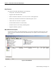
Chapter 1 – About OPC and the OPC Data Manager OPC Server Directories The OPC Server Directories show the OPC servers and items that the OPC Data Manager can access. The left OPC Server Directory includes information for event servers. Icons next to the server names indicate whether the server is an OPC data server or an OPC event server . Data Manager Groups The Data Manager Groups section shows the groups that are currently defined.
Chapter 1 – About OPC and the OPC Data Manager 12 Siemens Building Technologies, Inc.
Chapter 2 – System Architecture Chapter 2 – System Architecture Chapter 2 contains the following topics: • System Components • System Recommendations System Components To establish communication between OPC servers, you need OPC compliant servers, the OPC Data Manager, Insight software with the OPCServer Option, and either an MEC, MBC, or a Soft Controller. Figure 3 shows the connections between each system component. Figure 3. System Component Connections.
Chapter 2 – System Architecture Virtual Points In an MEC, MBC, or a Soft Controller, virtual points hold the information received from OPC items on third-party servers. You must create a virtual point for each third-party OPC item that you want to monitor with Insight software. Follow these guidelines while creating virtual points via Insight software: • Plan point pairings. For each third-party OPC item (AO, AI, DO, DI) that you want to monitor or command, create a virtual point of the same type.
Chapter 3 – Setting Up the OPC Data Manager Chapter 3 – Setting Up the OPC Data Manager Chapter 3 contains the following topics: • Before You Install the OPC Data Manager • Installing the OPC Data Manager • Setting and Removing the OPC Data Manager as a Windows Service • Distributed COM (DCOM) • Starting the OPC Data Manager Manually • Opening and Closing the Main Window • Entering OPC Data Manager Settings • Setting Advanced System Configuration • Stopping the OPC Data Manager Before You
Chapter 3 – Setting Up the OPC Data Manager Filename Description PSTCFG.exe Matrikon OPC server configuration shell. OPCAuto.dll OPC automation library. PSTcfgps.dll Proxy library for the OPC Data Manager server configuration. opc_aeps.dll Proxy library for OPC Alarm and Events interface. opccomn_ps.dll Proxy library for OPC common interface opcproxy.dll Proxy library for OPC custom interface. Opcenum.exe OPC server enumerator. hinstall.exe Hardware key setup utility. ExprEval.
Chapter 3 – Setting Up the OPC Data Manager 3. Click OK. OPC Data Manager configuration is unaffected when you remove it from Windows services. You can still run the OPC Data Manager as a normal program. Distributed COM (DCOM) DCOM is an object protocol that enables COM components, including the OPC Data Manager, to communicate directly with each other across a network. The OPC Data Manager uses the same general DCOM settings as the Insight OPCServer.
Chapter 3 – Setting Up the OPC Data Manager Opening and Closing the Main Window You use the main window of the OPC Data Manager to do the following: • Enter OPC Data Manager settings. • Create groups to organize shared points in the OPC Data Manager. • Create shared points that establish communication between OPC items. • Define statistics to gather information about group and point activity.
Chapter 3 – Setting Up the OPC Data Manager 3. In the Configuration File section, do any of the following: • Auto-load config file on startup—If you want the Data Manager to load a certain configuration file automatically, select this checkbox, and then type, or click name.
Chapter 3 – Setting Up the OPC Data Manager 5. In the Check OPC Servers section, do any of the following: • Check OPC servers every—Type the number of minutes that should pass between the times when the OPC Data Manager checks OPC servers. • Attempt to restart dead OPC servers—Select this checkbox to make the OPC Data Manager try to restart an OPC server that seems to have failed. 6. Do one of the following: • To enter more settings, click another tab in the Data Manager Settings dialog box.
Chapter 3 – Setting Up the OPC Data Manager Backup Operation An OPC Data Manager can be configured in one of three redundancy settings: Primary, Hot, or Warm backup. Figure 4 shows the connections (lines) and data transmissions (arrows) for each redundancy setting. Primary Hot Backup Primary Warm Backup ODM ODM ODM ODM OPC OPC OPC OPC Figure 4. Backup Operation. • A Primary OPC Data Manager operates normally.
Chapter 3 – Setting Up the OPC Data Manager Table 2. Icon Colors for Redundancy Status. Color Message Meaning Grey No redundancy Redundancy has not been enabled. Yellow Waiting The Data Manager is in the initial “Wait time before detecting” phase. Green Alive time ago The sibling last sent a heartbeat time ago. This is less than the preset failure time. Red Down for time The sibling last sent a heartbeat time ago. This is greater than or equal to the preset failure time.
Chapter 3 – Setting Up the OPC Data Manager 4. In the Communication with Sibling ODM section, do all of the following: a. In the first field, type the name of the computer that has the other OPC Data Manager. b. In the second field, type the number of seconds that should pass between “heartbeats.” c. In the third field, type the maximum number of seconds that can pass without receiving a heartbeat before the OPC Data Manager determines that its sibling has failed. d.
Chapter 3 – Setting Up the OPC Data Manager 6. To set Synchronous mode, add the following in the Synchronous OPC section: • Insight.OPCServerDA • Insight.OPCServerDA.1 • LocalHost 7. Do one of the following: • To enter more settings, click another tab in the Data Manager Settings dialog box. • To save the information and close the Data Manager Settings dialog box, click OK.
Chapter 3 – Setting Up the OPC Data Manager In the log configuration file, all log settings have the following requirements: • They must be preceded by a hyphen (-). • They cannot be preceded by white space. • They must be followed by a carriage-return. Each setting is identified by a single letter and followed immediately by its new value. Accessing OPC Server Configuration Panels From the main window, you can access OPC server configuration panels, by doing the following steps: 1.
Chapter 3 – Setting Up the OPC Data Manager 26 Siemens Building Technologies, Inc.
Chapter 4 – Configuring Groups, Shared Points, and Statistics Chapter 4 – Configuring Groups, Shared Points, and Statistics Chapter 4 contains the following topics: • Overview • Variant Data Types • Using OPC Data Manager Data Files • Creating and Managing Groups • Adding and Modifying Shared Points • Adding and Removing Statistics Overview A valid OPC Data Manager configuration consists of groups and shared points. Groups organize shared points into logical categories.
Chapter 4 – Configuring Groups, Shared Points, and Statistics Description Data Type Value VT_BOOL Boolean (TRUE = -1, FALSE = 0) 11 VT_I1 1 byte signed character 17 VT_UI1 1 byte unsigned character 18 VT_UI2 2 byte unsigned integer 19 VT_UI4 4 byte unsigned integer 20 VT_ARRAY Array of values. Not supported. +8192 Using OPC Data Manager Data Files The OPC Data Manager uses data files to hold information about groups, points, and statistics.
Chapter 4 – Configuring Groups, Shared Points, and Statistics Creating and Managing Groups You must create a group before you can create shared points. Creating and Modifying Groups To create or modify a group, do the following steps: 1. Do one of the following: • To add a group, click • To modify a group, right-click the group in the Data Manager Groups section, and then click Properties. The Data Manager Group Properties dialog box opens. . The Add Data Manager Group dialog box opens. 2.
Chapter 4 – Configuring Groups, Shared Points, and Statistics The group appears as a folder in the Data Manager Groups section of the main window. a uni-directional group. indicates a bi-directional group. indicates Saving and Exporting Groups You can save and export group information. When you save group information, you add it to the current data file. If you want to save the information for a particular group only, you can export that information to a separate .csv file.
Chapter 4 – Configuring Groups, Shared Points, and Statistics Refreshing Group Information You can manually refresh, or request an update for, group information. This may be necessary if another client is connected to the OPC Data Manager or to update group information after importing a group. To refresh group information, do the following steps: 1. In the Data Manager Groups section, right-click the group, and then point to Refresh Group. 2.
Chapter 4 – Configuring Groups, Shared Points, and Statistics Figure 6 shows the communication flow for a uni-directional point in which the point value is transferred from a third-party system to the APOGEE Automation System. You should create this type of unidirectional point for a third-party OPC item that you want to monitor, but not command, with Insight software. Figure 6. Third-party Output to APOGEE Input.
Chapter 4 – Configuring Groups, Shared Points, and Statistics If you want to: Enable values and commands to be transferred in both directions between a virtual point and an OPC item on a third-party server. Then create a: Bi-directional point that has a virtual point as its Master (input) and a third-party OPC item as its Slave (output). A maximum of 200 points per group is recommended. To add a shared point to a group, do the following steps: 1.
Chapter 4 – Configuring Groups, Shared Points, and Statistics • Dead Value—Leave Do nothing selected. • DDE—If you want the point to be visible to DDE clients, select the Server to DDE checkbox. The point can be accessed from a DDE client by using the following syntax: DataManager|hub!groupitem. The DDE topic name is “hub” unless specified otherwise by the “-t” startup parameter to the Data Manager. The DDE item name is the concatenation of the group and shared point tags. 4.
Chapter 4 – Configuring Groups, Shared Points, and Statistics • Quality Pass-Through—If you want the OPC quality (GOOD, BAD, UNCERTAIN) of the input OPC Item to be written to an output item, select the Write OPC Qualities to this item checkbox, and then type the location and name of the OPC item that will hold the quality. • Action—If you want to assign an action to the shared point, select the type from the Action Type list. Actions are triggered when a value is written to the shared point. 5.
Chapter 4 – Configuring Groups, Shared Points, and Statistics Table 6. Statistic Types. Type Description POINTWRITEERRS • Total number of write errors (BAD quality writes) by a point. Source Group or Point—Type, or click statistic is requested. to browse for, the group or point name for which the If you type the name of the source point, be sure to precede the point name with its group name and a back slash, for example Group1\point1. • Destination Point—Type, or click will be written.
Chapter 5 – Troubleshooting Chapter 5 – Troubleshooting Chapter 5 contains the following topics: • Error Messages • Browsing Issues • OPC Item Issues • Redundancy Issues Error Messages Table 7 lists common error messages and solutions for those errors. Table 7. Error Messages. Error Message Unable to open the access token of the current thread Explanation and Solution Appears while creating a point that includes an OPC item on a remote server.
Chapter 5 – Troubleshooting OPC server is listed in the browse panel, but cannot be browsed. The OPC browse interface on OPC servers is an optional feature. Not all OPC servers support it. You can, however, still create shared points with OPC items from a non-browseable server by manually entering the item ID in the Add Shared Point dialog box. Consult the vendor supplied OPC server manual for the item ID syntax of your OPC server.
Appendix A – OPC Quality Flags Appendix A – OPC Quality Flags The OPC quality flags represent the quality of an item’s data value. The lower byte is a bit-field used to convey standard quality values. The high byte is available for vendor-specific use complementary to the standard values. The following table lists the range of valid quality values (ignoring the vendor-specific bits). See the OPC DA 2.0 specification for more information. Table 8. Valid Values for OPC Quality.
Appendix A – OPC Quality Flags 40 Binary Decimal 11011000 216 Definition Good, Local Override Description The value has been overridden and forced to a manually entered setting. Siemens Building Technologies, Inc.
Appendix B – Device Versus Cache Reads Appendix B – Device Versus Cache Reads When an OPC client creates a group and adds items to it, the OPC server attempts to retrieve values for active items from its data source. Internally, the OPC client maintains a data "cache," which it attempts to update at least as fast as indicated by the update rate of the group. The server optimizes regular communication with its data source for best performance while keeping the cache "fresh.
Appendix C – Data File Specifications Appendix C – Data File Specifications The OPC Data Manager uses a standard comma−separated (*.CSV) file format. Each file can have lines for groups, points, statistics, event subscriptions, and event mappings. Group Information The following table describes the contents of lines that describe groups.
Appendix C – Data File Specifications Point Information The following table describes the contents of lines that describe points. For example, the line POINT,group1\itemtag2,"Any Reference String",\\TREVOR-KIZIAK \Matrikon.OPC.Simulation\Random.Int1,,VT_I1,,,,,,,,,,,VT_EMPTY,0,0,0,0,,NONE,,,,,,,, defines an OPC Data Manager point named itemtag2, in unit group1. It will have its input side tied to item Random.Int1 on the Matrikon.OPC.
Appendix C – Data File Specifications Position Field Description 17 Dead value type. Must be one of VT_I2, VT_I4, VT_R4, VT_R8, VT_CY, VT_DATE, VT_BSTR, VT_BOOL, VT_I1, VT_UI1, VT_UI2, VT_UI4. See the Variant Data Types section. 18 Scaling parameter: Input minimum 19 Scaling parameter: Input maximum 20 Scaling parameter: Output minimum 21 Scaling parameter: Output maximum 22 Quality Tag, format: Host_Name\ProgId_of_OPC_Server\OPC_Item 23 Action type.
Glossary Glossary A Asynchronous mode In this mode, the OPC Data Manager can submit multiple write requests to the Insight OPCServer without having to wait for the “Write was Successful” signal from the OPCServer. During times of extended, numberous COVs, this can cause a problem, in which the COV data backs up and the processing time increases for each new COV. B bi-directional Information can be transmitted in two directions—from the Master OPC item to the Slave OPC item, and vice versa.
Glossary heartbeat Signal that one OPC Data Manager sends to another to indicate that it is functioning. Hot Backup Used for redundancy. Backup OPC Data Manager that operates normally except it does not write to the OPC servers until the primary OPC Data Manager fails. L LAN Local Area Network. Data communications network linking computers and nodes, usually within one building or campus. It is typically an Ethernet or Token Ring protocol.
Glossary S SCADA Supervisory Control and Data Acquisition. Typically, the software application that resides in a computer, supervising a variety of controllers and handling data acquisition. Synchronous mode In this mode, the OPC Data Manager must wait for the “Write was Successful” signal from the OPCServer after each COV write request. This prevents a backup of COV data and maintains optimal performance.
Index Index A A&E Subscriptions section.....................................11 Access Path Delimiters...........................................23 Active, field ............................................................29 application files ......................................................15 Asynchronous mode .........................................23, 45 Attempt to restart dead OPC servers, field .............20 Auto-load config file on startup, checkbox ............19 B backup OPC Data Manager ...
Index OPC standard............................................................9 opening data files....................................................28 Output OPC Server, section ...................................33 Output to File, field ................................................19 P points .............................................. See shared points primary OPC Data Manager...................................20 R recommendations....................................................
Siemens Building Technologies Inc. 1000 Deerfield Parkway Buffalo Grove, IL. 60089-4513 U.S.A. 1-847-215-1000 www.sbt.siemens.com © 2005 Siemens Building Technologies, Inc. Country of Origin: U.S.A.