
Data Sheet for Product


Engineering notes
Base frame
The room operator unit is designed for flush mounting or cavity-wall mounting in
conjunction with base-frames and cover plates from various manufacturers:
− SIEMENS-DELTA futura
− VIMAR idea
− Bticino Classic
− GEWISS Playbus
− AVE Systema 45
Up to 5 room operator units may be connected to one room controller.
The maximum permitted current associated with the supply voltage from the HRC3..
room controller must not be exceeded.
For further information, see data sheets N6313 and N6314.
The room temperature control algorithm is not in the room operator unit itself, but in the
controller application. To enable the room controller to communicate with the room
operator unit, the latter must be assigned with an address.
A
ddressing
The addresses of the room operator units are defined by their ID number, and the
temperature measurement function is enabled by setting the MST flag. The factory
settings are always ID = 1 and MST = 0.
In a control loop with several room operator units, the temperature is measured in one
device only (the master). The MST flag (MST = 0) determines whether the room
operator unit should measure the temperature, or whether it is a slave device
(MST = 1), in which case the temperature sensor is disabled.
− First room operator unit ID=1 MST=0 Master (sensor enabled)
− Second room operator unit ID=2 MST=1 Slave
− Third room operator unit ID=3 MST=1 Slave
− Fourth room operator unit ID=4 MST=1 Slave
− Fifth room operator unit ID=5 MST=1 Slave
Further control loops can also be defined by means of a special application in the room
controller. In such cases, other room operator units measure the temperature on the
same room bus.
Several control loops
Example with two control loops:
− First room operator unit for control loop 1 ID=1 MST=0
− Second room operator unit for control loop 2 ID=2 MST=0
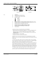
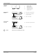
After a power failure, the room operator unit can be set to initialization mode by
operating the keys in the following sequence approximately 6 to 12 seconds after
power has been restored to the room controller or room operator unit:
Changing ID and MST
1. Hold down key 7
2. Hold down key 4
3. Release key 7
4. Release key 4
The current device address will now be displayed, alternating with the letters "Id". The
value can be modified with the "Minus" and "Plus" keys (keys 2 and 3).
After setting the required ID number, the ID number setting is confirmed with key 6.
The current MST number will now be displayed, alternating with the letters "MST". The
value can be modified with the "Minus" and "Plus" keys (keys 2 and 3).
4/8
Siemens HTC3.1/A, HTC3.1S/A – Room operator units CM2N6319en
Building Technologies 31.07.2008