
Data Sheet for Product

Engineering notes
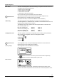
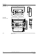
Base frame The room unit is designed for flush wall mounting in conjunction with base-frames and
cover plates from various manufacturers:
• Bticino Living for HTC3.2/BB
• Bticino Light for HTC3.2/BW
• Vimar Idea for HTC3.2/VB
• Vimar Plana or Ikon for HTC3.2/VW
Up to 4 room units may be connected to one room controller.
STOP
Important note
The maximum permitted current associated with the supply voltage from the
HRC3.1/HRC3.2 room controller must not be exceeded.
(For further information, see data sheet CM2N6313 and CM2N6314.)
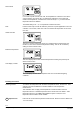
Addressing
The room temperature control algorithm is not in the room unit itself, but in the
controller application. To enable the room controller to communicate with the room unit,
the latter must be assigned with an address.
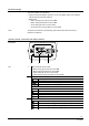
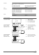
The addresses of the room operator units are set by DIP switch on the back of the
room comfort operator unit.
First room operating unit ADR0=0, ADR1 = 0
Second room operating unit ADR0=1, ADR1 = 0
Third room operating unit ADR0=0, ADR1 = 1
Fourth room operating unit ADR0=1, ADR1 = 1
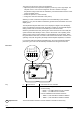
Configuration menu The room operator unit includes a configuration menu for setting certain parameters.
After a restart, the configuration menu can be displayed as follows:
1. Hold down
2. Press and hold
3. Release
4. Release
STOP
Important note
The configuration menu can only be displayed provided that no other buttons are
pressed when the room operator unit is restarted.
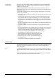
The configuration menu is identified as shown below.
Opening display
+
6320Z03
The
buttons are used to move to the previous and next menu respectively.
The
+
buttons are used for settings within a given menu.
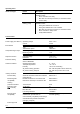
Room sensors
+
6320Z04
For room temperature measurement, the internal or external room sensor can be
selected. The default is temperature measurement via the internal temperature sensor.
5/10
Building Technologies HTC3.2/.. - Room operator unit CM2N6320en
01.09.2008