
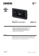
User Manual
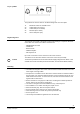


Key to symbols
The symbols are shown in white on the black background of the front plate.
T1 Membrane switch for doorbell feature
V3 Yellow LED (room service)
V5 Yellow LED (do not disturb)
V2 Red LED (door closed)
V6 Green LED (door open)
Engineering notes
The magnetic card reader is designed for flush wall mounting in conjunction with base-
frames and cover-frames from various manufacturers:
− SIEMENS-DELTA futura
− VIMAR idea
− Bticino Classic
− GEWISS Playbus
− AVE Systema 45
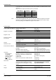
Up to four card readers can be connected to the same room bus.
The address is set with 2 DIL switches on the back of the unit (see below).
STOP
Caution
The maximum permitted current associated with the supply voltage from the HRC3.. room
controller must not be exceeded (for further information, see data sheets N6313, N6314.)
Mounting
• The HMR3.1/A magnetic card reader must be mounted outside the hotel room at the
same height as the light switch.
• First press the card holder into the base-frame and then attach the adhesive label to
the front plate. If the front-plate label is fitted first, it is then difficult to press the card
holder into the base-frame. To remove the unit, it must be unscrewed from the wall
together with the base frame.
• Ensure that there is enough spare cable in the mounting box to allow operation of
the DIL switches on the PCB (for addressing).
• The device is designed for fixed installation in a dry, enclosed space.
• For installation in a 4-module mounting box, depth 70 mm
• Mount horizontally only, with the front plate vertical
• Do not install AC 230 V devices in the same mounting box
• Commissioning must be carried out by trained personnel only
• Do not open the unit
• Local safety and installation regulations must be observed
3/6
Siemens HMR3.1/A – Magnetic card reader CM2N6334en
Building Technologies 31.07.2008