SIMATIC 505 High Speed Counter and Encoder Module User Manual Order Number: PPX:505–8113–2 Manual Assembly Number: 2586546–0019 Second Edition
Copyright 1992 by Siemens Industrial Automation, Inc. All Rights Reserved — Printed in USA Reproduction, transmission or use of this document or contents is not permitted without express consent of Siemens Industrial Automation, Inc. All rights, including rights created by patent grant or registration of a utility model or design, are reserved. Since Siemens Industrial Automation, Inc.
Contents Chapter 1 Overview 1.1 Features . . . . . . . . . . . . . . . . . . . . . . . . . . . . . . . . . . . . . . . . . . . . . . . . . . . . . . . . . . 1-2 1.2 Inputs . . . . . . . . . . . . . . . . . . . . . . . . . . . . . . . . . . . . . . . . . . . . . . . . . . . . . . . . . . . . 1–4 1.3 Outputs . . . . . . . . . . . . . . . . . . . . . . . . . . . . . . . . . . . . . . . . . . . . . . . . . . . . . . . . . . . 1–5 1.4 LED Indicators . . . . . . . . . . . . . . . . . . . . . . . . . .
Chapter 4 4.1 Checking the Operation of the Module . . . . . . . . . . . . . . . . . . . . . . . . . . . . . Chapter 5 5.1 5-2 5-3 Flow Rate Example . . . . . . . . . . . . . . . . . . . . . . . . . . . . . . . . . . . . . . . . . . . . . . . . 5-5 Description . . . . . . . . . . . . . . . . . . . . . . . . . . . . . . . . . . . . . . . . . . . . . . . . . . . . . . . . . . . Solution . . . . . . . . . . . . . . . . . . . . . . . . . . . . . . . . . . . . . . . . . . . . . . . . . . . . . . . . . . .
List of Figures 1-1 1-2 1-3 1-4 1-5 1-6 1-7 High Speed Counter Module . . . . . . . . . . . . . . . . . . . . . . . . . . . . . . . . . . . . . . 1-3 Output . . . . . . . . . . . . . . . . . . . . . . . . . . . . . . . . . . . . . . . . . . . . . . . . . . . . . . . . . . . 1-5 High Speed Counter LEDs . . . . . . . . . . . . . . . . . . . . . . . . . . . . . . . . . . . . . . . . . 1-6 Pulse Counter Mode 0 . . . . . . . . . . . . . . . . . . . . . . . . . . . . . . . . . . . . . . . . . . . . .
List of Tables 1-1 Determining Count in Pulse Counter Mode . . . . . . . . . . . . . . . . . . . . . . . . . 1-7 B-1 B-2 Environmental Specifications . . . . . . . . . . . . . . . . . . . . . . . . . . . . . . . . . . . . . . Electrical Specifications . . . . . . . . . . . . . . . . . . . . . . . . . . . . . . . . . . . . . . . . . . .
Chapter 1 Overview 1.1 Features . . . . . . . . . . . . . . . . . . . . . . . . . . . . . . . . . . . . . . . . . . . . . . . . . . . . . . . . . . 1-2 1.2 Inputs . . . . . . . . . . . . . . . . . . . . . . . . . . . . . . . . . . . . . . . . . . . . . . . . . . . . . . . . . . . . 1-4 1.3 Outputs . . . . . . . . . . . . . . . . . . . . . . . . . . . . . . . . . . . . . . . . . . . . . . . . . . . . . . . . . . . 1-5 1.4 LED Indicators . . . . . . . . . . . . . . . . . . . . . . . . . . . . . . .
1.1 Features The Series 505 High Speed Counter (HSC) module (PPX:505-7002) provides two independent high-speed counter channels. Each channel has the following features. Four counter modes: Pulse counter Quadrature counter modes: 1X, 2X, 4X A 10 kHz count rate with a minimum pulse width of 25 s. Four inputs: two count inputs reset inhibit Two field outputs, each controlled by a separate programmable preset.
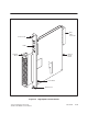
Base Plane Connector Bezel Screw LEDs Printed Circuit Board Terminal Block Front Bezel Bezel Screw Figure 1-1 High Speed Counter Module Series 505 High Speed Counter and Encoder Module User ’s Manual Overview 1-3
1.2 Inputs The HSC module has two independent channels. Each channel has four inputs. Reset Inhibit Two counter inputs Each input may be used as either sinking or sourcing (with external 5–24 VDC power supply). The input signals are connected to the field wiring terminal block on the front bezel. Counter InputsąEach channel has two counter inputs — Input A and Input B. Reset Current flow through the reset input sets the channel’s counter to zero.
1.3 Outputs Each channel has two open collector outputs capable of driving TTL level signals or sinking up to 0.4 Amps of current (at 40_C) from an external 24 VDC source and load. Y Output Output Return Output Circuit Y2 Y1 0 P1 P2 65,535 Counter Value Figure 1-2 Output The output transistor (Y1 or Y2) turns on when the count is greater than or equal to the corresponding preset. Figure 1-2 shows the field output operation.
1.4 LED Indicators Each channel contains four LED indicators which provide a visual indication of the channel’s status as shown in Figure 1-3. Figure 1-3 High Speed Counter LEDs A Turns on when there is current flow through the A input. B Turns on when there is current flow through the B input. Y1 Turns on when Output 1 is on. Y2 Turns on when Output 2 is on. NOTE:ăIf Reset or Inhibit is turned on, the HSC does not count, and the A and B LEDs are frozen.
1.5 Counting Modes 1.5.1 Pulse Counter Mode Each channel has two inputs, A and B. In the pulse counter mode, counting occurs on the rising or falling edge of the incoming pulses. The relationship of the states of these two inputs determines the direction of the count. See Table 1-1. Typical devices for counting are high-speed static switches or incremental encoders.
Counting Modes (continued) 1.5.2 Quadrature Mode 1.5.3 1X Quadrature For quadrature mode, each channel counts according to rising and/or falling edges. Typical devices for quadrature inputs are optical encoders. Different quadrature modes are selected based on the resolution required by the application and the encoder used. The module counts on the edges of the A input pulses. When input A leads input B, the HSC counts up on each rising edge of input A.
1.5.4 2X Quadrature If input A leads input B, the module counts up on both the rising and falling edges of input A. If input B leads input A, the module counts down on the rising and falling edges of input A. Figure 1-6 illustrates the relationship between inputs A and B and the count value in the 2X quadrature mode. 2X Quadrature Count Value 1 2 3 4 3 2 1 0 A B 25 s min 26.
Counting Modes (continued) 1.5.5 4X Quadrature If input A leads input B, the module counts up on rising and falling edges of both input A and input B. If input B leads input A, the module counts down on the rising and falling edges of input A and input B. Figure 1-7 shows the relationship between inputs A and B and the count value in the 4X quadrature mode. 4X Quadrature Count Value 1 2 3 4 5 6 7 8 7 6 5 4 3 2 1 0 A B 25 s min 26.
Chapter 2 Installation 2.1 Before Installing the Module . . . . . . . . . . . . . . . . . . . . . . . . . . . . . . . . . . . . . . . 2.1.1 Visual Inspection . . . . . . . . . . . . . . . . . . . . . . . . . . . . . . . . . . . . . . . . . . . . 2.1.2 Additional References . . . . . . . . . . . . . . . . . . . . . . . . . . . . . . . . . . . . . . . 2.1.3 Handling the Module . . . . . . . . . . . . . . . . . . . . . . . . . . . . . . . . . . . . . . . . 2.1.4 General Wiring Considerations . . . . . . . .
2.1 Before Installing the Module 2.1.1 Visual Inspection 2.1.2 Additional References 2.1.3 Handling the Module If there is any visible damage to the module, contact your Siemens Industrial Automation, Inc. distributor for replacement. Refer to the manuals listed below for instructions on installing, programming, and troubleshooting your Series 505E controller.
2.1.4 General Wiring Considerations The count, inhibit, and unfiltered reset inputs are high-speed inputs which may respond to noise present on the lines. To avoid problems, follow these guidelines when installing the HSC module. D Use the shortest possible wires. D Avoid placing signal wires parallel to high-energy wires. If the two must meet, cross them at right angles. D Avoid bending the wire into sharp angles. D Use wireways for wire routing.
Before Installing the Module (continued) 2.1.5 Hierarchy of Installation Figure 2-1 provides a simple flowchart of the installation process.
2.2 Selecting Counter Operation 2.2.1 Selecting Counter Mode The HSC module has two channels. You can configure each channel to operate in any of four counter modes. Prior to installing the module into the I/O backplane, configure the module by setting the jumper for each channel. Figure 2-2 shows the location of the jumpers on the printed circuit board. The top set of four pins set the counter mode for Channel 1. The bottom set of four pins set the counter mode for Channel 2.
Selecting Counter Operation (continued) 2.2.2 Selecting the Reset Filter Some applications require faster response on the reset input line than the standard 3.75-ms filter allows. For faster response, select the optional 0.95-ms filter. (The 0.9-ms filter is more sensitive to noisy signals, as noted in the Environmental Specifications in Appendix B.) The reset filter may be selected independently for each input channel by placing the jumper in the (fast) or (slow) position as shown in Figure 2-2.
2.3 Inserting the Module in the I/O Base The HSC is a single-wide module. Insert it into any available slot on any Series 505 I/O base. Do not touch the printed circuit board while inserting the module. This could cause electrostatic damage to the components on the board. Insert the module as shown in Figure 2-3. ! To minimize potential shock, turn off power to the I/O base and any modules installed in the base before inserting or removing a module.
2.4 Wiring the Module 2.4.1 Wiring the Terminal Block Wiring the module consists of wiring the the input and output signals. See Figure 2-4 and Figure 2-5 for general guidelines. All connections are made at the module terminal block. See Figure 2-5. Output returns for Channel 1 and 2 are internally connected. Use the Terminal Block Worksheet in Appendix B for planning your wiring. ! 2.4.
5–24 VDC Sinking Driver Ch1 A– Ch1 A+ Ch1 B+ Ch1 B– Ch1 RST+ Encoder Ch1 RST– Ch1 INH+ Ch1 INH– 5–24 VDC +– Ch1 Y1 Ch1 Y2 5–24 VDC Ch2 A+ Sourcing Driver Ch2 A– Ch2 B+ Ch2 B– Ch2 RST+ Ch2 RST– Ch2 INH+ Ch2 INH– 5–24 VDC +– Ch2 Y1 Ch2 Y2 Figure 2-5 Sample Terminal Block Wiring Diagram Series 505 High Speed Counter and Encoder Module User ’s Manual Installation 2-9
2.5 Logging the Module into the Controller 2.5.1 Updating the I/O Configuration Definition 2.5.2 Selecting the I/O Configuration After inserting the module into the base, update the I/O configuration in the controller. The module does not automatically onfigure itself. A VPU or other programming device must be connected to the controller to register and verify controller module communication. With your VPU or other programming device, select the I/O Configuration option.
2.5.3 Viewing the I/O Configuration Chart Use SHOW to view the I/O Configuration Chart. If the HSC is installed in slot 1, for channel 1, base 00, the I/O chart will appear as displayed in Figure 2-7.
Chapter 3 Programming 3.1 Controller Input Words . . . . . . . . . . . . . . . . . . . . . . . . . . . . . . . . . . . . . . . . . . . . . . 3-2 3.1.1 3.1.2 3.1.3 3.1.4 3.1.5 WX1 (Status Word) . . . . . . . . . . . . . . . . . . . . . . . . . . . . . . . . . . . . . . . . . . . . . . . . . . . . WX2 and WX3 (Channel Count) . . . . . . . . . . . . . . . . . . . . . . . . . . . . . . . . . . . . . . . WY4 (Setup Word) . . . . . . . . . . . . . . . . . . . . . . . . . . . . . . . . . . . . . . . . . . . . .
3.1 Controller Input Words The HSC module is configured as three word inputs (WX) and five word outputs (WY). It occupies eight words of the controller’s word image register. 3.1.1 WX1 (Status Word) Word 1 (WX) is the module’s status word. Eight bits provide the status of each of the two channels. Figure 3-1 shows the format of the status word.
Inhibit Status. Each channel has an Inhibit Status bit in the status word. If the channel’s Inhibit field input is active or if its Inhibit Command bit is 1 (see Setup Word, Section 3.1.3), this bit will be 1 and the counter will not count. Otherwise, this bit will be 0. Output Status. Each channel has an Output 1 Status and an Output 2 Status bit in the status word. If the corresponding field output is on, the bit will be 1. Otherwise, the bit will be 0. 3.1.2 WX2 and WX3 (Channel Count) 3.1.
Controller Input Words (continued) Reset Command. Both channels have a Reset Command bit. A transition from 0 (off) to 1 (on) of the Reset Command acts as a one-shot (providing a momentary reset of the channel), setting the count to 0. Even though the bit remains 1, counting resumes. Inhibit Command. Both channels have an Inhibit Command bit. When this bit is set to 1, the channel stops counting.
Chapter 4 Troubleshooting Symptom Input LED is not on and Output LED is not on Probable Cause No power to board Corrective Action Re-seat board Check for bent pins on board connector Problems with input signals, or output being reset or inhibited Check your base power supply Check wiring Check encoder or field inputs Check Reset and Inhibit bits in Setup word (WY4) Counts in wrong direction Connections wrong Reverse wiring for inputs A and B Input wires substantially different lengths Check that w
4.1 Checking the Operation of the Module To check the operation of the module, follow these steps. Module outputs will turn on during this procedure. 1. Using a programming device, force all presets to 0. 2. Reset both counters through the reset signals from your application. Using the default configuration, the outputs should turn on. 3. Using your programming device, force the presets to any number greater than 0. The outputs should turn off.
Chapter 5 Applications 5.1 Sprayer Example . . . . . . . . . . . . . . . . . . . . . . . . . . . . . . . . . . . . . . . . . . . . . . . . . . 5.1.1 5.1.2 5.2 Description . . . . . . . . . . . . . . . . . . . . . . . . . . . . . . . . . . . . . . . . . . . . . . . . . . . . . . . . . . . . . . Solution . . . . . . . . . . . . . . . . . . . . . . . . . . . . . . . . . . . . . . . . . . . . . . . . . . . . . . . . . . . . . . . . . 5-2 5-3 Flow Rate Example . . . . . . . . . . . . . . . . . . . . . . .
5.1 Sprayer Example 5.1.1 Description A reversible DC motor drives a paint sprayer up and down a vertical assembly. A quadrature encoder on the drive shaft senses the direction and relative position of the sprayer. Channel 1 of the HSC will be used to enable the sprayer during a pre-defined section of travel. (See Figure 5-1.) The encoder resolution is 500 cycles per revolution. One shaft revolution equals 1 inch of sprayer travel. When encoder signal A leads, the direction of travel is up.
5.1.2 Solution Connect encoder signals A and B to inputs A and B of the HSC. See Figure 5–2. Limit switch 1 (sprayer home) drives channel 1 Reset. Channel 1 outputs 1 and 2 are wire ORed and drive the sprayer enable. Select 1X Quadrature mode for channel 1, setup channel 1 output 1 to turn off when count preset, output 2 to turn on when count preset. Presets 1 and 2 are loaded with the Start Sprayer and Stop Sprayer counts, respectively.
Sprayer Example (continued) C1 C14 CLEAR CHANNEL 1 SETUP WORD SETUP CHANNEL 1 OUTPUT 2 TO GO LOW AT PRESET LDC1 BITS1 SELECT COUNT INHIBIT ON CHANNEL 1 BITS2 A: WY4 A: WY4 A: WY4 N= 0 N= 4 N= 2 LOADS CHANNEL 1 PRESETS 1 & 2 FROM V200 & V201 INHIBIT CHANNEL 1 BIT IS CLEARED COUNTING IS ENABLED MOVW1 C12 C15 BITC23 A: B: V200 WY5 A: WY4 N= 2 N= 2 Figure 5-4 Ladder Logic for Sprayer Example 5-4 Applications Series 505 High Speed Counter and Encoder Module User ’s Manual
5.2 Flow Rate Example 5.2.1 Description 5.2.2 Solution A flow meter outputs 200 pulses per gallon. The program requires calculation of flow rate in gallons per minute (GPM). Configure the HSC as WX9–WX11, WY12–WY16. Attach channel 1 to the flow meter. The HSC accumulates flow meter pulses for the duration of a 1-second fast timer. In the controller, accumulated pulses are scaled to GPM by the following calculation (using the controller memory locations).
5.3 Tank Filling Example 5.3.1 Description The HSC module measures the volume of liquid and control the filling valve. (See Figure 5-6.) A flow meter, generating 200 pulses per gallon, is connected to the HSC channel 2, input A. Output 2 controls the filling valve. In this example, the HSC operates in the pulse counter mode. Solution A count of 100,000 pulses is required to fill the tank to 500 gallons.
C140 C140 IS USED TO INITIATE/TERMINATE FILLING C140 X128 C140 C1 C256 : RESET HSC, LOAD INITAL PRESETS C140 C1 Y20 LDC4 A: WY4 N=0 C141 BITS1 A: WY4 N=5 MOVW1 A: V200 B: WY7 N=2 : CLEAR RESET BIT C141 C1 BITC1 A: WY4 N=5 Y20 : ENABLE LIQUID FLOW Y20 C1 Y20 C140 Figure 5-7 Ladder Logic for Tank Filling Example Series 505 High Speed Counter and Encoder Module User ’s Manual Applications 5-7
Tank Filling Example (continued) C61 : ACCUMULATE THE OVERCOUNTS C61 C51 SUB1 ADD1 A: WX3 A: V101 B: V200 B: V100 C: V101 C: V100 : AFTER 90,000 PULSES, SUBTRACT THE OVERCOUNTS FROM 10,000 AND LOAD THE REMAINING COUNT INTO PRESET 2. C8 C8 C51 CTR2 SUB2 P= 9 C140 MOVW2 A: V200 A: V201 B: V100 B: WY7 C: WY8 N=1 C256 C8 : TEST FOR COMPLETION OF 100,000 COUNTS, INHIBIT FURTHER COUNTS, AND CLEAR OVERCOUNT ACCUMULATOR. C256 WILL THEN TURN OFF C140 AND DISABLE THE VALVE.
Appendix A Terminal Block Worksheet Series 505 High Speed Counter and Encoder Module User ’s Manual Terminal Block Worksheet A-1
Appendix B Specifications B.1 Environmental Specifications . . . . . . . . . . . . . . . . . . . . . . . . . . . . . . . . . . . . . . B-2 B.2 Electrical Specifications . . . . . . . . . . . . . . . . . . . . . . . . . . . . . . . . . . . . . . . . . . . B-3 B.3 Additional Compliances . . . . . . . . . . . . . . . . . . . . . . . . . . . . . . . . . . . . . . . . . . .
B.
B.2 Electrical Specifications Table B-2 Electrical Specifications Count Inputs Frequency (maximum) Duty Cycle Count Mode Freq. 10% 20% 25% 30% 40% 50% 60% Quadrature Mode Freq. (w/ 15 max. phase error) 10 Khz 25 Khz 30 Khz 35 Khz 50 Khz 45 Khz 35 Khz On voltage: Current on: Off voltage: Current off: 4 Khz 8 Khz 10 Khz 12 Khz 15 Khz 15 Khz 15 Khz 4 to 28 VDC, Class 2 supply 8 to 16 mA –1.5 to 1.
Electrical Specifications (continued) Count inputs are constant current type inputs. Reset and Inhibit Inputs: On voltage: to 28 VDC, Class 2 supply Current on: 2 to 40 mA Off voltage: –1.5 to 1.5 VDC Current off: 0 to 0.75 mA Reset delay time: unfiltered 950 s on 950 s off filtered 3.75 ms on 5.
Outputs User voltage: . . . . . . . . . . . . . . . . . . . . . . . . . 28 VDC max. Voltage drop: . . . . . . . . . . . . . . . 1.8 VDC max. @ 400 mA 1.0 VDC max. @ 25 mA Leakage current: . . . . . . . . . . . . . 500 A max. Peak current: . . . . . . . . . . . . . . . . 500 mA for 1 ms Output current: 400 1 Point per channel I(mA) 300 275 mA 2 Points per channel 200 175 mA 100 20 40 60 80 100 T ( C) Isolation: User-side to P/C-side . . . . . . . . . . . . . . . . . . . .
B.3 Additional Compliances In addition, the system complies with applicable requirements of Verband Deutscher Elektrotechniker (VDE) 0160: Electrical Equipment Series 505 products have been developed with consideration of the draft standard for programmable controllers as described in the proposed standard of the International Electrotechnical Commission Committee (IEC–65A/WG6, Part 2). Information concerning product reliability and compliance to the IEC or other standards can be provided upon request.
Customer Registration We would like to know what you think about our user manuals so that we can serve you better. How would you rate the quality of our manuals? Excellent Good Fair Poor Accuracy Organization Clarity Completeness Overall design Size Index Would you be interested in giving us more detailed comments about our manuals? Yes! Please send me a questionnaire. No. Thanks anyway.
FOLD NO POSTAGE NECESSARY IF MAILED IN THE UNITED STATES BUSINESS REPLY MAIL FIRST CLASS PERMIT NO.3 JOHNSON CITY, TN POSTAGE WILL BE PAID BY ADDRESSEE SIEMENS INDUSTRIAL AUTOMATION, INC. 3000 BILL GARLAND RD. P.O.
Index A Assistance, 2-2 C Configuration selecting, 2-10 updating, 2-10 Configuring jumpers, 2-5 User Options, 2-10 Count input, 1-4 Count rate, 1-2 Counter mode, 1-7 I I/O address, 2-10 configuration chart, 2-11 definition chart, 2-10 I/O base, 2-7 Inhibit, 1-2, 1-4 Input, 1-4 count, 1-4 inhibit, 1-4 reset, 1-4 Specifications, B-3 J Jumper, 2-5 Jumper pins, 2-5 D Double-count quadrature, 1-9 E L LED, 1-2 A input, 1-6 B input, 1-6 LED indicator, 1-6 Logging module into controller, 2-10 Electrical spec
Q Quadrature Mode, quadruple count, 1-10 Quadrature mode double-count, 1-9 single-count, 1-8 T Terminal block, 2-8 wiring diagram, 2-9 worksheet, 2-8 Quadruple count, quadrature mode, 1-10 R References, 2-2 U Using status words, 3-2 Reset, 1-2, 1-4 S Single-count quadrature, 1-8 Static electricity, 2-2 Index-2 W Wiring, 2-3, 2-8 considerations, 2-3
SIMATIC is a registered trademark of Siemens AG. Series 505 and TISOFT are trademarks of Siemens Industrial Automation, Inc. Texas Instruments and TI are registered trademarks of Texas Instruments Incorporated. TI505, TI525, TI535, and TI545 are trademarks of Texas Instruments Incorporated. UL is a registered trademark of Underwriters Laboratories.