
User Manual

Mechanical design
Construction The chipcard holder consists of:
• Component assembly (carrier, printed circuit board, four LEDs, membrane switches,
chipcard reader-unit, terminal block and DIP switch)
• Base frame
− Bticino Living/Type L4703 for HCH3.2/BB
− Bticino Light/Type N4703 for HCH3.2/BW
− Vimar Idea/Type 16713 for HCH3.2/VB
− Vimar Plana or Ikon/Type 20613 for HCH3.2/VW
The component assembly is permanently glued into the base frame and cannot,
therefore, be replaced.
Display Depending on the standard application configured in the HRC3.1/HRC3.2 room
controller, the following room states can be displayed:
• Do not disturb
• SOS, Call for assistance, Room service
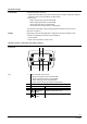
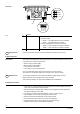
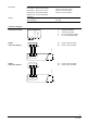
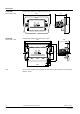
Operator controls, connections and display elements
21
6333Z01de
V1 V2
T2
T1
Front view
1 Base frame with fixing screws
• Bticino Living/Type L4703 for HCH3.2/BB
• Bticino Light/Type N4703 for HCH3.2/BW
• Vimar Idea/Type 16713 for HCH3.2/VB
• Vimar Plana or Ikon/Type 20613 for HCH3.2/VW
2 Card slot backlit with 3 green LEDs
V1 Yellow LED Room service call
V2 Yellow LED
Do not disturb
T1
Membrane
switch
Activates room service call
T2
Membrane
switch
Activates "Do not disturb"
Key
3/8
Building Technologies HCH3.2/.. - Chipcard holder with doorbell speaker CM2N6333en
01.09.2008