
Data Sheet for Product


12
Siemens
CM2N4658en
Smart Infrastructure
2021-10-26
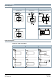
GMA161.9E
GMA161.9E/MO
Modulating control DC 0…10 V
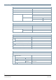
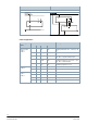
Cable designations
Connecting
thread
Cable
Meaning
Code
No.
Color
Abbreviation
Rotary actuators
AC 24 V ~
DC 24 V =
G
1
Red
RD
System potential AC 24 V ~ / DC 24 V...48
V =
G0
2
Black
BK
System neutral
Y1
6
Purple
VT
Positioning signal AC 0 V, AC 24 V ~ / DC
24…48 V = "Counter-clockwise" NC.
Y2
7
Orange
OG
Positioning signal AC 0 V, AC 24 V ~ / DC
24…48 V = "Clockwise" NC.
Y
8
Gray
GY
Positioning signal DC 0...10 V
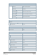
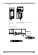
Rotary actuators
AC 230 V ~
U
9
Pink
PK
Position indication 0...10 VDC
L
3
Brown
BN
Phase AC 230 V
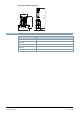
Modbus
AC 24 V ~
DC 24 V =
N
4
Blue
BU
Neutral conductor
REF
6
Purple
VT
Reference line (Modbus RTU)
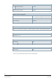
+
8
Gray
GY
Bus + (Modbus RTU)
-
9
Pink
PK
Bus - (Modbus RTU)