
Basic Documentation


26/44
Siem ens GMA..1 actuators with spring return CM2Z4614en
Building Technologies 2018-01-11
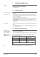
The diagram shows the currents in the connecting lines for one actuator.
0 V
DC 24 V
DC 0...10 V
DC 1 mA
GMA16..1
M
G0
G
Y
U
1
2
9
8
(DC 0...10 V)
DC 0.15 A
DC 0.15 A
DC 0.1 mA
4614G08en
Determining the line lengths for four actuators GMA16..1, GMA19...1 at DC 24 V
supply. Only the DC currents in line 1 (G) and 2 (G0) determine the line sizing.
Line 2 (G0): (max. voltage drop 1 %) Line 1 (G): (max. voltage drop 4 %)
∂ Consumption: 4 x 3.5 W = 14 W
∂ Line current: 4 x 0.15 A = 0.6 A
∂ Permissible single line length:
13 m at 1.5 mm
2
line cross section or
22 m at 2.5 mm
2
line cross section.
∂ Consumption: 4 x 3.5 W = 14 W
∂ Line current: 4 x 0.15 A = 0.6 A
∂ Permissible single line length:
141 m at 1.5 mm
2
line cross section or
235 m at 2.5 mm
2
line cross section.
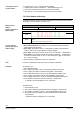
6.5 Actuator wiring (Modbus RTU)
The damper actuators are supplied with a prewired connecting and communication
cable. All interconnected devices must be connected to the same G0.
Strand code Strand color Terminal code Description
1 red (RD) G System potential
AC 24 V ~ / DC 24 V
⎓
2 black (BK) G0 System neutral
6 violet (VT) REF Reference (Modbus RTU)
8 grey (GY) + Bus + (Modbus RTU)
9 pink (PK) - Bus - (Modbus RTU)
The operating voltage at terminals G and G0 must comply with the requirements under
SELV or PELV.
Safety transformers with twofold insulation as per EN 61558 required; they must be
designed to be on 100 % of the time.
P&I diagram:
Conduction currents at
DC 24 V
Example:
Parallel connection of four
actuators
Note