
Data Sheet for Product

3 / 14
A6V10636203_en--_f Siemens
2021-11-08 Smart Infrastructure
GLB..
AC 24 V ~ /
DC 24…48 V
⎓
141.9E 161.9E ─
AC 24 V ~ /
DC 24 V
⎓
─ ─ 161.9E/MO
AC 100…240 V ~ 341.9E ─ ─
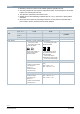
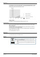
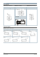
Position indication: Mechanical Rotary angle position indication by a position indicator/hand lever.
Position indication: Electrical
Output voltage U = DC 0/2...10 V is generated proportional to
the rotary angle.
U depends on the rotary direction of the DIL switch setting.
Self-adaptation of rotary angle span When self-adaption is active, the actuator automatically detects
mechanical end of the rotary angle range.
Manual adjustment The rotary actuator can be manually adjusted by pressing the gear train disengagement button.
Rotary angle limitation The rotary angle of the shaft adapter can be limited mechanically with a set screw.
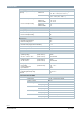
Modbus RTU (RS-485), not
galvanically isolated
Setpoint 0...100 %
valve position
Actual value 0...100 % for
valve position
Override control Open / Close
/ Min / Max / Stop
Setpoint monitoring and
backup mode
Technical design/mechanical design
Housing
The housing consists essentially of flame retardant, non brominated, non chlorinated glass
fibre reinforced plastic.
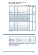
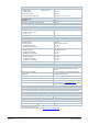
Type summary
Type Stock no. Control Operating
voltage
Position indicator
U = DC 0…10 V
⎓
Self-adaption of
rotational angle
range
Aux.
switches
Rotary
direction
switch
GLB141.9E S55499-D204
Open-close or
three-position
AC 24 V ~ /
DC 24…48 V
⎓
‒ ‒ ‒
yes
GLB341.9E S55499-D205 AC 100…240 V ~
GLB161.9E S55499-D277
Modulating
DC 0/2...10 V
⎓
AC 24 V ~ /
DC 24…48 V
⎓
yes yes ‒
GLB161.9E/MO S55499-D681 Modbus RTU
AC 24 V ~ /
DC 24 V
⎓