
Basic Documentation


26 / 42
Siemens VAV Compact Controller Modbus RTU A6V10631862_en--_e
Smart Infrastructure 2021-10-26
6 Engineering and commissioning
6.1 Fundamentals / environments
For this chapter, sufficient knowledge about Modbus RTU communication and
suitable controllers are presupposed.
6.2 Engineering
The basic task of engineering comprises implementation of the data model into a
VAV application, especially setpoint and actual values (flow and position) for
monitoring and optimization. System limitations of Modbus RTU / RS-485 apply,
especially number of devices per segment and cable lengths depending on the
baudrate.
The data model is documented as Modbus register list, cf. 9.1 .
6.3 Commissioning
6.3.1 Preconditions
The beginning of the commissioning phase assumes that all VAV Compact
Controllers are mounted according to the mounting instruction [2] as well as all
other devices according to their mounting instructions.
All devices must be connected to the power supply and bus cabling. Power supply
and bus cabling must be tested, especially the communication between setpoint
sender and setpoint receiver.
Commissioning of VAV Compact Controllers consists of two parts:
• Commissioning of the VAV control function (cf. sections 5.1 and 5.1.2),
• Commissioning of the network integration.
Two basic workflows are supported:
• Full or partial configuration (bus configuration and optionally VAVconfiguration)
by a tool (AST20 or ACS941),
• Full or partial configuration over bus, optionally with addressing by push-
button.
6.3.2 Workflow 1: Full or partial configuration by tool
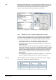
When using the AST20 handheld tool or the ACS941 PC tool, all bus parameters
and VAV Compact Controller parameters can be set.
• Connect AST20 or ACS941 (using the AST22 interface converter) to the VAV
controller and navigate to the bus configuration menu,
• Set bus parameters as desired,
• Optionally make changes on VAV controller parameters in VAV configuration
menu.
Preconditions
Commissioning
preconditions