
Basic Documentation


12 / 42
Siemens VAV Compact Controller Modbus RTU A6V10631862_en--_e
Smart Infrastructure 2021-10-26
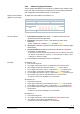
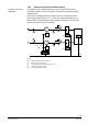
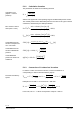
2.5 Internal diagrams
The VAV Compact Controller is supplied with two prewired connecting and
communication cables.
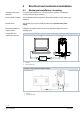
Tool = Configuration and maintenance interface
(7-pin)
Core designation
Core color
Terminal code
Description
Cable 1: Power / black sheathing
1
red (RD)
G
System voltage AC 24 V
2
black (BK)
G0
System neutral AC 24 V
Cable 2: Communication / blue sheathing
6
violet (VT)
REF
Reference
8
grey (GY)
+
Bus (Modbus RTU)
9
pink (PK)
-
Bus (Modbus RTU)
Terminal layout may differ for each device. Devices with twin-terminals or internally
connected terminals may be encountered as well as bus connection in junction
boxes.
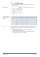
• The operating voltage at terminals G and G0 must comply with the
requirements under SELV or PELV.
• Safety transformers with twofold insulation as per EN 61558 required; they
must be designed to be on 100 % of the time.
Internal diagram
Power supply and bus
cable (color coded and
labeled)
Note