Modbus RTU OpenAirTM VAV Compact Controller Modbus RTU G..B181..
Issued by Siemens Switzerland Ltd Smart Infrastructure Global Headquarters Theilerstrasse 1a 6300 Zug Switzerland Tel. +41 58-724 24 24 www.siemens.com/buildingtechnologies 2 / 42 Siemens Smart Infrastructure © Siemens Switzerland Ltd, 2015 Technical specifications and availability subject to change without notice.
Table of contents 1 Introduction..........................................................................................4 1.1 Revision history .....................................................................................4 1.2 Before you start .....................................................................................4 1.3 Objectives of this basic documentation...................................................5 1.4 Referenced documents ...........................................
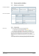
1 Introduction 1.1 Revision history Version e Date 2021-10-26 Changes Adaptive positioning Section 2 Device 6 Parameterization and operating modes 10 Datapoints and function description d c 2019-09-13 2018-04-16 2 Device 2 Device b 2016-02-26 AST22 replaces AST11 LED colors and patterns updated, internal diagrams EU and RCM Conformity, European Directive 2012/19/EU a 2015-07-20 9 Technical data, 11 Environmental compatibility and disposal 1.2 Before you start 1.2.
1.2.4 Document use / request to the reader Before using our products, it is important that you read the documents supplied with or ordered at the same time as the products (equipment, applications, tools etc.) carefully and in full. We assume that persons using our products and documents are authorized and trained appropriately and have the technical knowledge required to use our products as intended.
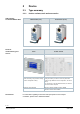
VAV Compact Controller Modbus RTU Tools for commissioning and service 2 Device 2.1 Type summary 2.1.1 Device variants, tools and accessories GDB181.1E/MO (5 Nm) AST20 The handheld tool AST20 can be used for status monitoring, VAV parameter setting, and bus configuration setting. GLB181.1E/MO (10 Nm) ACS931 / ACS941 The PC software for service ACS941 can be used for setting and reading a certain set of device parameters (values set by OEM and current configuration, and actual values).
2.1.
2.1.3 Version summary The production series can be identified by the letter behind the code “2PFS”. Identification Version Series A Production time Features Until Sept. 2017 ▪ Communication Modbus RTU ▪ Quasi-static differential pressure sensor. ▪ Simultaneous feedback of actual values of damper position and air volume flow. ▪ Optional adaptive opening range measurement (adaptive positioning). ▪ HMI with push button and LED. Series B From Sept.
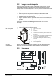
2.2 Design and device parts The VAV Compact Controllers consist of a differential pressure sensor, actuator and digitally configurable control electronics. They are intended for mounting on damper shafts of a minimum length of 30 mm. They consist of base and 2-sectional housing. Components contained in the base: • Steel base plate with damper drive shaft fixing for different drive shaft diameters / cross-sectional areas (cf. section 2.
Push button operations LED colors and patterns 2.4 Human-machine interface 2.4.
2.4.3 Addressing by push-button The bus address (RS-4895) can be set without a separate tool by using the pushbutton and LED. For instructions on setting VAV and communication parameters with configuration and maintenance tools, cf. section 5.1.2. Display current address. (digits in reverse order) To display the current address, press button <1s.
2.5 Internal diagrams The VAV Compact Controller is supplied with two prewired connecting and communication cables.
2.6 Measuring principle A measuring device for acquiring the differential pressure – usually a measuring cross, measuring orifice or Venturi tube in the airflow – represents the basis for air volume flow measurement. Differential pressure sensor The air volume flow is measured indirectly with a differential pressure sensor. Since the measured value is the differential pressure p, the air flow is derived from this value using the VAV box characteristic.
Application 3 Functionality / application 3.1 Fields of application VAV Compact Controllers are primarily used for controlling a variable or constant air volume flow.
3.2.2 Example: AHU control optimization Demand-controlled ventilation (DCV) In combination with a suitable supervisory room controller, an AHU control optimization algorithm can be run using the actual value of the damper position feedback signal. The control of variable speed drives (VSDs) can be accomplished by various means. Below depicted is DC 0...
4 Electrical and mechanical installation 4.1 Mechanical installation / mounting Mounting and mounting limitations For mounting and limitations on mounting (location / position), consulting the mounting instruction [2] is mandatory. Environmental conditions The permissible ambient temperature and ambient humidity must be observed (cf. chapter 8). Manual control The actuator may only be manually operated when separated from power supply.
4.2 Electrical installation / cabling 4.2.1 Power supply cabling Permissible cable lengths and crosssectional areas The permissible cable lengths and cross-sectional areas depend on the actuators’ current draw and the voltage drop on the connecting lines to the actuators. The necessary cable lengths can be determined from the following chart or with the help of the formulas. Cf. also to technical data in section 8.
Formula for cable length The following formula can be used to calculate the maximum cable lengths.
Parameterization and operating modes 5 5.1 Settings and user interaction 5.1.1 Device parameters Parameterization The OEM generally provides the basic configuration to VAV Compact Controllers, esp. the parameters Vn and Vnom. The basic configuration is independent of the system environment where the VAV Compact Controllers are to be used. For parameter setting, configuration and maintenance tools as described in section 5.1.2 are available.
5.1.2 Calculation formulas The parameters are based on the following formulas: Calculation of Vn (Δpnom = nominal pressure) 𝑉𝑛 = √ 300 [𝑃𝑎] ∆𝑝𝑛𝑜𝑚 [𝑃𝑎] 300 Pa is the upper limit of the operating range of the differential pressure sensor. The nominal pressure is the differential pressure in the VAV box at a given nominal volume flow, determined by the OEM specification. Min. and max. volume flows (Vmin / Vmax) 𝑉𝑚𝑖𝑛 [%] = 𝑚𝑖𝑛. 𝑣𝑜𝑙𝑢𝑚𝑒 𝑓𝑙𝑜𝑤 [𝑚3 ⁄ℎ] ∙ 100% 𝑛𝑜𝑚. 𝑣𝑜𝑙𝑢𝑚𝑒 𝑓𝑙𝑜𝑤 [𝑚3 ⁄ℎ] 𝑚𝑎𝑥.
5.2 Configuration and maintenance tools Configuration and maintenance of VAV Compact Controllers can be accomplished with the following tools: • Using the PC software ACS941or ACS931 together with the interface converter AST22 via the configuration and maintenance interface of the VAV Compact Controller or • Using the handheld tool AST20. 5.2.
5.3 Setting examples 5.3.1 Symbols and parameters Volume symbols with “point” ( V ) and without point (V) shall have the same meaning, i.e., they all shall refer to volume flows.
Setting example A2 VAV ratio control, 20 % constant excess supply air volume flow (positive pressure in the room) Supply air Extract air Vmin Vmax Vmin Vmax Supervisory controller 20 % 80 % 0% 60 % VAV Compact Controller 0% 100 % 0% 100 % Reference signal: Ysupply_air = 35 %, Yextract_air = Ysupply_air - 20 % = 15 % Result: Vsupply_air = 35 %, Vextract_air = 15 % Supply air controller Extract air controller V max V min V max V min V 120 120 100 100 80 60 60 40 40 20
5.3.3 Min/max control by the VAV Compact Controller When setting the minimum / maximum air volume flow in the VAV Compact Controller, the supervisory controller must be set to Vmin= 0% und Vmax = 100 %. With this setting, the supervisory controller reference signal for both the supply air and extract air controller is the same. Thus, supply air / extract air control with a single reference signal is possible.
Setting example B2 VAV ratio control, 20 % constant excess supply air volume flow (positive pressure in the room) Supply air Extract air Vmin Vmax Vmin Vmax Supervisory controller 0% 100 % 0% 100 % VAV Compact Controller 20 % 80 % 0% 60 % Reference signal: Ysupply_air = Yextract_air = 25 % Result: Vsupply_air = 35 %, Vextract_air = 15 % Supply air controller Extract air controller V max V min V max V min V 120 120 100 100 80 60 60 40 40 V 100 100 80 80 60 V su
Preconditions 6 Engineering and commissioning 6.1 Fundamentals / environments For this chapter, sufficient knowledge about Modbus RTU communication and suitable controllers are presupposed. 6.2 Engineering The basic task of engineering comprises implementation of the data model into a VAV application, especially setpoint and actual values (flow and position) for monitoring and optimization.
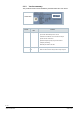
Note With AST20, all parameters can be set using the mass configuration function. The bus parameters are included in the mass programming routine. It can be selected that the address is automatically incremented with each programmed VAV controller. ACS941 supports saving and loading of parameter sets. ENTER ↓ Figure 2: Bus configuration with AST20 (left) and with ACS941 (right) 6.3.
7 Safety and EMC optimization 7.1 Safety notes This section contains general regulations and the regulations for mains and operating voltage. It also provides important information regarding your own safety and that of the entire plant. Safety note The warning triangle to the left means that observance of all relevant regulations and notes is mandatory. If ignored, injury to persons or damage to property may result.
Operating voltage AC 24 V Regarding AC 24 V operating voltage, the following regulations must be complied with: Regulation Operating voltage The operating voltage must comply with the requirements for SELV or PELV: AC 24 V • Permissible deviation of AC 24 V nominal voltage at the actuators: +/–20 % Specification on AC 24 V transformers • Safety isolating transformers as per EN 61558, with double insulation, designed for 100 % on time to power SELV or PELV circuits • Determine the transformer’s out
7.3 Notes on EMC optimization Running cable in a duct Make sure to separate high-interference cables from equipment susceptible to interference. Cable types • Cable causing interference: Motor cables, especially motors used with VSDs, energy cables. • Cables susceptible to interference: Control cables, low-voltage cables, interface cables, LAN cables, digital and analog signal cables. • You can run both types of cable in the same duct, but in different compartments.
8 Technical data Power supply Operating voltage G..B181.. AC 24 V ± 20 % (SELV) or AC 24 V class 2 (US) Frequency Power consumption 50/60 Hz at 50 Hz Actuator holds 1 VA/0.5 W Actuator rotates 3 VA/2.5 W Function data Positioning time for nominal rotation angle G..B181.. Nominal torque GDB.. 5 Nm GLB.. 10 Nm GDB.. < 7 Nm GLB.. < 14 Nm Maximum torque 120 s (60 Hz) Nom. / max.
Degree of protection Degree of protection Degree of protection acc. to EN 60529 (see mounting instruction) IP54 Safety class Safety class acc.
9 Datapoints and function description 9.1 Device Parameters (ACS931 / ACS941 / AST20) Parameter Range Description Factory setting Setpoint 0..100% Setpoint to VAV controller. 0% → Vmin N/A 100% → Vmax Actual position 0..100% Damper position, depends on setting for position adaptation N/A Actual Flow abs. 0..65’535 m3/h Actual volume flow in m3/h or l/s N/A Actual Flow % 0..100% Actual volume flow relative to Vnom in % N/A Actual pressure 0..
9.2 Modbus Registers For detailed descriptions of the function behind a certain item, e.g. “how does RemoteFactoryReset in register 256 work”, please cf. section 9.3. 9.2.1 Reg. Process values Name R/W Unit Scaling Range / enumeration Process Values 1 Setpoint RW % 0.01 0..100 2 Override control RW -- -- 0 = Off / 1 = Open / 2 = Close 3 = Stop / 4 = GoToMin 5 = GoToMax 3 Actual position R % 0.01 0..100 4 Actual Flow [rel.] R % 0.01 0..120 3 5 Actual Flow [abs.
9.2.3 Reg. Device information Name R/W Value Example Device information 1281 Factory Index R Two bytes, each 00 5A → 00 “Z” coding an ASCII char.
9.3 Parameter and function description 9.3.1 Vnom (nominal volume flow) [m3/h or l/s] VAV boxes are ordered through an OEM according to the required nominal volume flow (Vnom) and min. / max. volume flow settings (Vmin / Vmax). The maximum volume flow for ventilating a room / zone can’t be higher than the nominal volume flow. 9.3.2 Vmin / Vmax (minimum / maximum volume flow) [%] These values limit the nominal volume flow by multiplying with Vnom. Their effect is described in chapter 5. 9.3.
9.3.5 Adaptive positioning 9.3.5.1 Function For VAV boxes and air dampers with an opening range smaller than 0...90°, the position setpoint and feedback signal can be adapted to 0...100%. • Adaptive positioning off: Position control / feedback relative to 0°…90°, →Example: 0° → 0%, 18° → 20%, 81° → 90% etc. • Adaptive positioning on: Position control / feedback relative to the mechanical lower / upper endstops which are determined in an adaptation run.
9.3.6 Device Jam • If an actuator can’t reach a target position due to a mechanical failure or an angle limitation screw, a device jam alarm is thrown. • The device jam is detected ca. 30s after the effective mechanical end stop (when lying before the target end stop) is reached. • After 30..35s the motor stops and the steady red LED indicates the device jam alarm until the blockage is physically removed.
9.3.10 Reset behavior The actuator supports the following re-initialization / reset behavior: • Local reset by push-button: cf. section 2.4.2 • Tool-reset, cf. section 5.1.2 • Remote reset: Using “RemoteFactoryReset” command. Effect of reset: • Process values: set to ex-works default values. • Parameters: - Application and actuator parameters are set to factory or OEM defaults, - Network parameters are reset only in case of local reset, not by remote reset (otherwise loss of communication).
10 General notes Environmental compatibility and disposal The products were developed and manufactured by using environmentally compatible materials and by complying with environmental standards. For disposal, please remember the following at the end of product life or in case of defects: • The products consist of plastics and materials such as steel, ferrite magnetic core, etc. and must not be disposed of together with domestic waste; this applies particularly to the printed circuit boards.
/ 42 Siemens Smart Infrastructure VAV Compact Controller Modbus RTU A6V10631862_en--_e 2021-10-26
Issued by Siemens Switzerland Ltd Smart Infrastructure Global Headquarters Theilerstrasse 1a 6300 Zug Switzerland Tel. +41 58-724 24 24 www.siemens.com/buildingtechnologies © Siemens Switzerland Ltd, 2015 Technical specifications and availability subject to change without notice.