
Basic Documentation


11 / 46
Siemens VAV compact controller KNX/PL-Link G..B181.1E/KN CE1P3547en
Smart Infrastructure 2021-10-252021-10-25
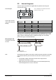
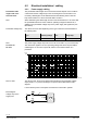
2.5 Internal diagrams
The VAV compact controllers are supplied with two prewired connecting and
communication cables.
Dp
(G) (CE+) (CE-)
1 1 2
(G0)
2
3547G01
Tool
Tool = Configuration and maintenance interface
(Series E and newer: 7-pin)
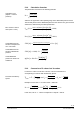
Core
designation
Core color
Terminal
code
Description
Cable 1: Power / black sheathing
1
red (RD)
G
System voltage AC 24 V
2
black (BK)
G0
System neutral AC 24 V
Cable 2: Bus / green sheathing
1
red (RD)
CE+
Bus (KNX / PL-Link)
2
black (BK)
CE-
Bus (KNX / PL-Link)
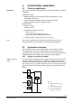
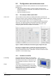
The VAV compact controllers are connected to the bus as KNX devices according
to the KNX-TP1 standard. KNX-specific limitations regarding cable length, power
supply, number of attachable devices, and distances apply. For more details,
please refer to [9] or to the KNX standard.
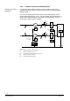
N1 G..B181.1E/KN
N2 VAV enabled room unit
Terminal layout may differ for each device. Devices with twin-terminals or internally
connected terminals may be encountered as well as bus connection in junction
boxes.
• The operating voltage at terminals G and G0 must comply with the
requirements under SELV or PELV.
• Safety transformers with twofold insulation as per EN 61558 required; they
must be designed to be on 100 % of the time.
G CE+ CE-
G0
N1
3547A01
G CE+ CE-
G0
X1 M U1 D1 GND
Y10 Y1 Y2
N2
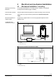
Internal diagram
Power supply and bus
cable (color coded and
labeled)
Wiring diagram VAV
Connection to the KNX
TP1-Bus
Note