
Data Sheet for Product


2 / 10
Siemens A6V10636203_enAP_d
Building Technologies 2018-01-25
Features
● Brushless, robust DC motors ensure reliable operation regardless of load.
● The rotary actuators do not require an end position switch, are overload proof, and remain
in place upon reaching the end stop.
● The gears are maintenance free and low noise.
● Suitable for use with modulating controllers (DC 0/2...10 V), open-close or three-position
controllers.
● We recommend a minimum pulse length of 500 ms on rotary actuators operated with 3-
point control to ensure continuous and accurate operation.
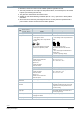
Functions
GLB..
AC 24 V ~ /
DC 24…48 V ⎓
141.9E 161.9E
AC 100…240 V ~ 341.9E ─
Control type Open-close / three-position Modulating control (0/2…10 V)
Rotary direction Clockwise or counter-clockwise direction depends …
… on the type of control
… on the setting of the rotary direction
DIL switch.
With no power applied, the actuator
remains in the respective position.
… on the setting of the rotary direction DIL
switch
… on the positioning signal.
The actuator remains in the achieved
position:
… if the control signal is maintained at a
constant value
… for loss of operating voltage.
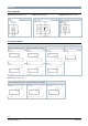
NC (normally closed) ball valve NC (normally closed) ball valve
Signal on Y1
– rotation counter-clockwise
– ball valve opens
Signal on Y2
– rotation clockwise
– ball valve closes
DIL 2 set to “counter-clockwise” (ccw)
Flow = 0% at Y = 0 V
Flow = 100% at Y = 10 V
NO (normally open) ball valve NO (normally open) ball valve
Signal an Y2
– rotation clockwise
– ball valve closes
Signal on Y1
– rotation counter-clockwise
– ball valve opens
DIL 2 set to “clockwise” (cw)
Flow = 100% at Y = 0 V
Flow = 0% at Y = 10 V
Position indication:
Mechanical
Rotary angle position indication by a position indicator/hand lever.
Position indication:
Electrical
Output voltage U = DC 0/2...10 V is
generated proportional to the rotary angle.
U depends on the rotary direction of the
DIL switch setting.
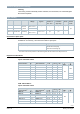
Self-adaptation of rotary
angle span
When self-adaption is active, the actuator
automatically detects mechanical end of
the rotary angle range.
Manual adjustment The rotary actuator can be manually adjusted by pressing the gear train
disengagement button.
Rotary angle limitation The rotary angle of the shaft adapter can be limited mechanically with a set screw.
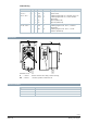
cw
ccw
G
D
.
.
1
E
_
Z
0
6
G
D
.
.
1
E
R
W
_
Z
0
8
cw
ccw
00...
2...
0
0...
2...