
Data Sheet for Product


13
Siemens
A6V12513940_en
--
_a
Smart Infrastructure
2021
-
06
-
17
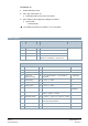
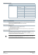
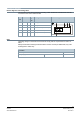
Connection diagrams
Device diagram / connecting cable
The actuators come with a prewired connecting cable. All devices connected to it must be
connected to the same neutral line G0.
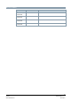
Wire
code
Wire color Termi-
nal
code
Meaning Connection diagram
1 red RD G Voltage phase AC 24 V
2 black BK G0 Voltage neutral line AC 24 V
6 violet VT REF Reference line (Modbus RTU)
8 gray GY + Bus + (Modbus RTU)
9 pink PK - Bus - (Modbus RTU)
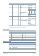
Note
Operating voltage on terminals G and G0 must comply with the requirements for SELV or
PELV.
Safety transformers featuring twofold insulation must be used as per EN 61558; they must
be designed for 100% duty.
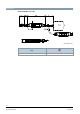
Connection
Cable length 0.9 m
Voltage supply / communication Wire number and diameter 5 x 0.75 mm
2