ACVATIX™ Rotary actuators for ball valves Modbus communication profiles Rotary actuators G../MO ● ● ● ● A6V12513940_en--_a 2021-06-17 GDB161.9E/MO operating voltage AC 24 V/ DC 24 V RS-485 for Modbus RTU communication GLB161.9E/MO Operating voltage AC 24 V/ DC 24 V RS-485 for Modbus RTU communication GLD161.9E/MO operating voltage AC 24 V/ DC 24 V RS-485 for Modbus RTU communication GMA161.
Use This document describes the network functions of the rotary actuators series G../MO. Functions Function Description Communication Modbus RTU (RS-485), not galvanically isolated Functions ● ● ● ● Supported baud rates 9.6 / 19.2 / 38.4 / 57.6 / 78.4 / 115.2 kBaud Transmission formats 1-8-E-1, 1-8-N-1, 1-8-O-1, 1-8-N-2 Bus termination 120 Ω electronically switchable Setpoint 0...100 % valve setting Actual value 0...
Product documentation Title Contents Document number Rotary actuators for ball valves GDB..9E.. Data sheet: Product description GDB..9E.. A6V10636150 Rotary actuators for ball valves GLB..9E.. Data sheet: Product description GLB..9E.. A6V10636203 Rotary actuators for ball valves GLD161.9E.. Data sheet: Product description GLD161.9E.. A6V11171770 Rotary actuators for ball valves GMA..9E.. Data sheet: Product description GMA..9E..
Commissioning The devices were developed specifically for use with Climatix pushbutton configuration as described in document CE1A3975 1). The bus configuration can alternatively be configured by the local HMI, see section User interface [▶ 5]. Check the following during commissioning: ● Bus configuration (address, baudrate, transmission mode, and optional bus termination). The default address 255 allows mounting and commissioning of multiple actuators at the same time without interfering with each other.
User interface Pushbutton operation Action Pushbutton operation Return current Modbus address (starting from lowest address position) Press button < 1 s Feedback message ● 1st digit (single digit): red ● 10-digit (double digit): green ● 100-digit (triple digit): orange LED blinks blue 1 x after the address indication if bus termination is switched on.
LED colors and flashing patterns Color Blinking pattern Description Green 1 s on / 5 s off Normal mode without bus traffic Flickering Normal mode with bus traffic Orange / green 1 s orange / 1 s green Device is in override control mode Orange 1 s on / 1 s off Bus parameter not yet configured 1 s on / 5 s off Device is in backup mode (replacement mode) Permanently lit Mechanical error, device blocked, manual intervention or calibration 1 s on / 5 s off Internal error 0.
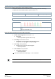
Enter address using pushbutton Display current address (starting from lowest address position) The Modbus address can be set without an extra tool using pushbutton addressing. To display the current Modbus address, press the button <1s. Colors 1-digit: red 10-digit: green 100-digit: orange Example for address 124: LED Note The address is entered and displayed beginning at the lowest digit (1st digit), see figure above.
Examples Set address „124“: 1. Enable addressing mode. 2. Set 1-digit: Press button 4 x. ● LED flashes rot for each press of the button. 3. Save 1-digit: Hold button. ● LED is lit green. – Release button. 4. Set 10-digit: Press button 2 x. ● LED flashes green for each press of the button. 5. Save 10-digit: Hold button. ● LED is lit orange. – Release button. 6. Set 100-digit: Press button 1 x. ● LED flashes orange for each press of the button. 7. Save address: Hold button. ● LED is lit rot.
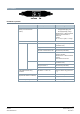
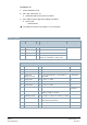
Set address „5“: 1. Enable addressing mode. 2. Set 1-digit: Press button 5 x.. ● LED flashes rot for each press of the button. 3. Save address (skip 10-digit and 100-digit): Hold button. ● LED is lit rot. – Release button. ⇒ The address is saved and is repeated 1 x for confirmation. Modbus registers Reg. Name R/W Range/Listing Factory setting Process values 1 Setpoint RW 0...100 % = 0...10000 2 Forced control RW 0 = Off / 1 = Open / 2 = Close / 3 = Stop 3 Actual Value R 0...100 % = 0.
Device information 1281 Index R Two bytes, each coding an ASCII character Example: 00 5A Æ 00 "Z" Device is of series "Z" 1282 Factory Date HWord R Two bytes, the lower coding the year (hex) Example: Reg. 1282 = 000F Reg.
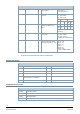
Communication properties Communication Communication protocol Modbus RTU RS-485, not galvanically isolated Number of nodes Max. 32 Address range 1...248 / 255 Factory setting 255 Transmission formats 1-8-E-1, 1-8-N-1, 1-8-O-1, 1-8-N-2 Factory setting 1-8-E-1 Baud rates (kbaud) Auto / 9.6 / 19.2 / 38.4 / 57.6 / 78.4 / 115.
Register 256 "Reset" The actuator supports the following reset/re-initialization behavior: ● Local reset by push-button ● Reset over bus with command "Remote-Reset" Effect of reset: ● Process values except actual value and setpoint are reset to factory settings. ● Network parameters (register 513...516 and 764...768) are only reset in case of a local reset. When resetting over the network, the network parameters are retained, as otherwise communication would be lost.
Connection diagrams Device diagram / connecting cable The actuators come with a prewired connecting cable. All devices connected to it must be connected to the same neutral line G0.
Dimensions External Modbus converter Dimensions in mm X [mm] [kg] 250 0.
Revision numbers Type Firmware version Valid from rev. no. GDB161.9E/MO S55499-D682 2.1 ..A GLB161.9E/MO S55499-D681 2.1 ..K GLD161.9E/MO S55499-D695 2.1 ..F GMA161.9E/MO S55499-D683 2.1 ..
Issued by Siemens Switzerland Ltd Smart Infrastructure Global Headquarters Theilerstrasse 1a CH-6300 Zug +41 58 724 2424 www.siemens.com/buildingtechnologies Document ID A6V12513940_en--_a Edition 2021-06-17 © Siemens Switzerland Ltd, 2021 Technical specifications and availability subject to change without notice.