
User Manual


5
Siemens Datasheet A6V11948472_en--_a
Smart Infrastructure 2020-05-28
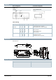
Diagrams
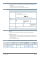
Internal Diagrams Connection diagrams
GED33..1A
AC 220 V ~
Three-position control
AC 220 V~
Cable labeling
Connection
Code
No
Color
Abbreviation
Meaning
Actuators
AC 220V
N
Y1
Y2
4
6
7
black
red
white
BK
RD
WH
Neutral conductor
Control signal AC 220 V, clockwise
Control signal AC 220 V, counter-clockwise
Auxiliary switch V
Q12
Q14
Q22
Q24
S2
S2
S1
S1
green
white
black
red
GN
WH
BK
RD
Switch neutral contactor
Switch contactor
Switch neutral contactor
Switch contactor
Feedback
a
b
c
P1
P2
P3
red
blue
blue
RD
BU
YE
Potentiometer 0...100 % (P1-P2)
Potentiometer pick-off
Potentiometer 100...0 % (P3-P2)
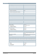
Dimensions
Dimensions in mm
Revision numbers
Type
Valid from rev. no.
GED331.1A
..A
GED332.1A
..A
GED336.1A
..A
A6 V1 19 48 472Z1 0