s OpenAir™ Air Damper Actuators Modbus RTU GEB.., GIB.. Non-spring return types Damper actuators 15 Nm / 35 Nm (non-spring return) with Modbus communication ● ● ● ● ● A6V101037253_en--_a 2017-02-17 GEB.. 15 Nm nominal torque GIB..
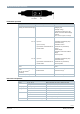
Functions Function Description Communication Modbus RTU (RS-485), not galvanically separated Functions - Setpoint and actual position 0..100% - Override control Open / Close / Min / Max / Stop - Setpoint monitoring and backup mode Supported baudrates 9.6, 19.2, 38.4, 57.6, 78.4, 115.2 kbaud Supported transmission formats 1-8-E-1, 1-8-N-1-, 1-8-O-1, 1-8-N-2 Termination 120 Ω electronically switchable Type summary Product no. Stock no. GEB161.1E/MO S55499-D298 GIB161.
Product documentation Title Topic Document ID Rotary damper actuators without spring return GEB.. Detailed information about rotary actuators (15 Nm) Z4621 Rotary damper actuators without spring return GIB.. Detailed information about rotary actuators (35 Nm) Z4626 Climatix AHU Application Application description A3975 Installation Instruction Installation of types with external Modbus interface A6V101006034 Related documents such as environmental declarations, CE declarations, etc.
Commissioning Workflow 1 The devices are especially designed for using the Climatix push-button configuration as de1) scribed in document A3975 . The bus configuration can alternatively be parameterized by the local HMI, cf. page 5. During commissioning check/set the following: ∂ Bus configuration (address, baudrate, transmission mode, and optionally termination). The default address 255 allows to mount and power multiple actuators at the same time without interfering with each other.
HMI (Human-Machine Interface) Push-button operation Activity Push-button operation Confirmation Display current address Press button < 1s 1-digits: red (starting with lowest address digit) 10-digits: green 100-digits: orange If termination is switched on, LED flashes 1x blue after address display Example: 124 = 4x red, 2x green, 1x orange Turn bus termination on / off turn on 1. press 3x LED flashing and flickering stops (termination mode) 2. press 1x shortly LED flashes 1x blue 3.
Resetting the device by push button 1. 2. 3. 4. Press button for >10s ⇓ LED starts flashing orange Release button while LED still flashes ⇓ LED keeps flashing for 3s If the button is pressed within these 3s, the reset is cancelled. After those 3s ⇓ LED shines red (reset), then the device restarts. Push-button addressing Display current address (starting with lowest address digit) The Modbus address can be set without a separate tool by using the push-button and LED.
Examples Set 1. 2. 3. 4. 5. 6. 7.
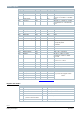
Modbus registers Reg. Name R/W Unit Scaling Range / enumeration Process Values 1 Setpoint RW % 0.01 0..100 2 Override control RW -- -- 0 = Off / 1 = Open / 2 = Close 3 = Stop / 4 = GoToMin / 5 = GoToMax 3 Actual position R % 256 Command RW -- 0.01 0..
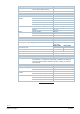
Supported function codes Function codes 03 (0x03) Read Holding Registers 04 (0x04) Read Input Registers 06 (0x06) Write Single Register 16 (0x10) Write Multiple registers (Limitation: Max. 120 registers within one message) Technical data Power supply Operating voltage G..B161.1E/MO Frequency Power consumption Actuator holds Actuator rotates AC 24 V ± 20 % (SELV) or AC 24 V class 2 (US) 50/60 Hz at 50 Hz GEB161.1E/MO 1.5 W GIB161.1E/MO 1.1 W GEB161.1E/MO 6 VA / 5.5 W GIB161.
Degree of protection Degree of protection Degree of protection acc. to EN 60529 (see also chapter ‘Mounting’ above) IP54 Safety class Safety class acc. to EN 60730 III Environmental conditions Applicable standard Operation Transport Storage IEC 60721-3-x Climatic conditions Class 3K5 Mounting location Indoors Temperature general -32…55 °C Humidity (non condensing) < 95 % r. h. Climatic conditions Class 2K2 Temperature -32…70 °C Humidity < 95 % r. h.
Diagrams Internal diagrams The damper actuators are supplied with a prewired connecting and communication cable. All interconnected devices must be connected to the same G0. Core desig.
Dimensions GEB.. 141 10.6 42 20 113 Dia.5 168 180 12 Dia. 6.4...20.5 Square 6.4...13 Dia.10.5 31.5 81 60 GEB...1 19 60 192 2 Taptite M6 x 16 4621M01en 3 15 30 30 Mounting bracket GIB.. 300 73 197 67.5 4x8,5 27,6 24,8 2 100 230 min. 100 3 min. 60 min. 200 4626M03 20 4x ø5 6x ø4,4 35,4 35,4 16 min. 7 ø13 Taptite M6 x 16 71 Ø 8... 25,6 mm ν 6... 18 mm 900 210 150 S1...S6 max.17,5 ma x . 95 ° 85,8 1...9 61,5 P1...
/ 14 A6V101037253_en--_a 2017-02-17 Siemens Building Technologies
Issued by Siemens Switzerland Ltd Building Technologies Division International Headquarters Gubelstrasse 22 6301 Zug Switzerland Tel. +41 41-724 24 24 www.siemens.com/buildingtechnologies Dokument-ID A6V101037253_en--_a Ausgabe 2017-02-17 © Siemens Switzerland Ltd, 2016 Technical specifications and availability subject to change without notice.