
Data Sheet for Product
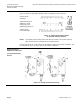

Technical Instructions OpenAir™ GDE Enhanced Non-Spring Return Rotary Electronic Damper Actuator
Document Number 155-784
January 20, 2017
Page 12 Siemens Industry, Inc.
Wiring,
continued
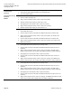
WARNINGS:
Installations requiring Conformance:
All wiring for CE certified actuators must be SELV or PELV rated per
HD384-4-41.
Use safety-isolating transformers (Class III transformer) per EN61558.
They must be rated for 100% duty cycle.
Over current protection for supply lines is maximum 10A.
Each wire has the standard symbol printed on it. See
Table 4.
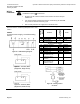
GDE14x
24 Vac/dc Power Supply, 2-Position/Floating
Control
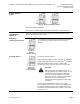
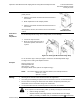
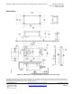
Figure 20. GDE14x Wiring Diagram.
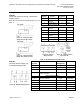
Figure 21. 2-Position, SPST
(Single-Pole, Single-Throw).
Figure 22. 2-Position, SPDT
(Single-Pole, Double-Throw).
Table 4. 2-Position/Floating Control 24 Vac/dc.
Standard
Symbol
Function
Terminal
Designation
Color
1
Supply (SP)
G
Red
6
Control signal clockwise
Y1
Violet
7
Control signal
counterclockwise
Y2
Orange
Factory-installed Options
S1
Switch A Common
Q11
Gray/red
S2
Switch A N.C.
Q12
Gray/blue
S3
Switch A N.O.
Q14
Gray/pink
S4
Switch B Common
Q21
Black/red
S5
Switch B N.C.
Q22
Black/blue
S6
Switch B N.O.
Q24
Black/pink
P1
Feedback Potentiometer
0 to 100% P1 - P2
(0 to 5,000 ohms)
a
Black
P2
Feedback Potentiometer
Common
b
Black
P3
Feedback Potentiometer
100 to 0% P3 - P2
(5,000 to 0 ohms)
c
Black
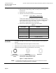
Figure 23. Floating Control
24 Vac/dc.