Technical Instructions Document No. 155-784 January 20, 2017 OpenAir™ Electronic Damper Actuators GDE Series Enhanced Non-spring Return Rotary Description The OpenAir direct coupled enhanced non-spring return rotary electric actuators are designed for two-position/floating or modulating control of dampers. Features Application These actuators are used in constant or variable air volume installations for control of HVAC dampers requiring up to 44 lb-in (5 Nm) of torque.
Technical Instructions OpenAir™ GDE Enhanced Non-Spring Return Rotary Electronic Damper Actuator Document Number 155-784 January 20, 2017 Specifications Operating voltage (G–G0) Power Supply Frequency Power consumption GDE14x GDE34x GDE16x Control signal Input signal (Y-G0) Voltage-input Feedback signal 24 Vac/dc +/-20% 100 to 240 Vac +/-10% 50/60 Hz VA Watt 2.0 1.0 5.0 1.6 2.1 1.
OpenAir™ GDE Enhanced Non-Spring Return Rotary Electric Damper Actuator Technical Instructions Document Number 155-784 January 20, 2017 Specifications, continued Housing Ambient conditions Agency certification Enclosure Material Gear lubrication NEMA Type 2 IP54 according to EN60529 (Not with cable-up mounting orientation.
Technical Instructions OpenAir™ GDE Enhanced Non-Spring Return Rotary Electronic Damper Actuator Document Number 155-784 January 20, 2017 Accessories, Continued ASK71.6: Allows economical mounting of an OpenAir actuator to a variety of surfaces. Figure 4. Rotary-to-Linear with Bracket. Should be used in applications where the actuator can be rigidsurface mounted and a linear stroke output is needed. ASK78.3U: Shaft inserts for use with 3/8-inch (8 to 10 mm) diameter shafts. (10/pk).
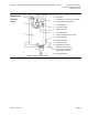
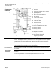
OpenAir™ GDE Enhanced Non-Spring Return Rotary Electric Damper Actuator Technical Instructions Document Number 155-784 January 20, 2017 Actuator Components Legend 2-Position/ Floating 2. Positioning scale for angle of rotation 1. Base plate 3. Rotation direction adjustment 4. Conduit adapter 5. Connection cable 6. Manual override 7. Coupling bushing 8. Factory-installed 1/2-inch guide 9. Auxiliary Switch A 10. Auxiliary Switch B 11. Position indicator 12.
Technical Instructions OpenAir™ GDE Enhanced Non-Spring Return Rotary Electronic Damper Actuator Document Number 155-784 January 20, 2017 Legend Actuator Components, Continued 1. Base plate 2. Positioning scale for angle of rotation Modulating 3. Span adjustment 4. Offset (start point) adjustment 5. DIP switches 6. Cover for DIP switches 7. Conduit adapter 8. Connection cable 9. Manual override 10. Coupling bushing 11. Factory-installed 1/2-inch guide 12. Auxiliary Switch A 13. Auxiliary Switch B 14.
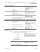
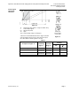
OpenAir™ GDE Enhanced Non-Spring Return Rotary Electric Damper Actuator Technical Instructions Document Number 155-784 January 20, 2017 Control signal adjustment, continued Figure 10. Ys Y Uo U Uw Positioning range (100% = angle of rotation 90°*) Control input signal Offset (start point) Span Active voltage range (Ys changes) * When the mechanical limitation of the angle of rotation and self-adapt function are ON, 100% does not equal 90°. Also valid for control signal 0 to 10 Vdc.
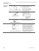
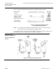
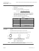
Technical Instructions OpenAir™ GDE Enhanced Non-Spring Return Rotary Electronic Damper Actuator Document Number 155-784 January 20, 2017 Auxiliary Switches GDE146.1P, GDE346.1U, GDE164.1P, GDE166.1P Figure 12 shows the adjustable switching values for Auxiliary Switches A and B. Actuator Scale: Clockwise Adjustment range for Switches A and B Setting interval: 5° Switching hysteresis: 2° Actuator Scale: Counterclockwise Figure 12. Adjustable Switching Values for the Dual Auxiliary Switches.
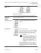
OpenAir™ GDE Enhanced Non-Spring Return Rotary Electric Damper Actuator Technical Instructions Document Number 155-784 January 20, 2017 Rotation Direction Switch Counterclockwise Clockwise Figure 14. Direction of Rotation Switch. The factory setting is clockwise. The direction of rotation switch should match the damper rotation movement. Dual in-Line Package (DIP) Switches GDE16x.1P Raise the protective cover from left to right to locate the DIP switches. See Figure 9 for the location of the cover.
Technical Instructions OpenAir™ GDE Enhanced Non-Spring Return Rotary Electronic Damper Actuator Document Number 155-784 January 20, 2017 The type of actuator required depends on several factors. Sizing 2 2 1. Obtain damper torque ratings (ft-lb/ft or Nm/m ) from the damper manufacturer. 2. Determine the area of the damper. 3.
OpenAir™ GDE Enhanced Non-Spring Return Rotary Electric Damper Actuator Manual Override Technical Instructions Document Number 155-784 January 20, 2017 To move the damper blades and lock the position with no power present: 1. Slide the red manual override knob toward the back of the actuator. 2. Make adjustments to the damper position. 3. Slide the red manual override knob toward the front of the actuator. Once power is restored, the actuator returns to automated control.
Technical Instructions OpenAir™ GDE Enhanced Non-Spring Return Rotary Electronic Damper Actuator Document Number 155-784 January 20, 2017 Wiring, continued WARNINGS: Installations requiring Conformance: All wiring for CE certified actuators must be SELV or PELV rated per HD384-4-41. Use safety-isolating transformers (Class III transformer) per EN61558. They must be rated for 100% duty cycle. Over current protection for supply lines is maximum 10A.
OpenAir™ GDE Enhanced Non-Spring Return Rotary Electric Damper Actuator Technical Instructions Document Number 155-784 January 20, 2017 Wiring, continued Table 5. Two-Position, Floating Control, 100 to 240 Vac. GDE34x 100 to 240 Vac Power Supply, Two-Position Floating Control Standard Symbol Each wire has the standard symbol printed on it. See Table 5.
Technical Instructions OpenAir™ GDE Enhanced Non-Spring Return Rotary Electronic Damper Actuator Document Number 155-784 January 20, 2017 Start-Up/ Commissioning 1. Connect a Digital Multimeter (DMM) to the supply voltage wires. 2. Verify that the supply voltage is between 19.2 and 28.8 Vac/dc. 24 Vac/dc 3. Turn off the power supply. Two-position/ Floating Check Operation: 24 Vac/dc 1. Connect all wires per Figure 20. GDE14x 2. Apply a control signal (24 Vac/dc) to wires 1 (red) and 6 (violet). 3.
OpenAir™ GDE Enhanced Non-Spring Return Rotary Electric Damper Actuator Start-Up/ Commissioning Technical Instructions Document Number 155-784 January 20, 2017 1. Connect a Digital Multimeter (DMM) to the supply voltage wires. 2. Verify that the supply voltage is between 100 and 240 Vac. 3. Turn off the power supply. Two-position/ Floating Check Operation: 100 to 240 Vac 1. Connect all wires per Figure 26. GDE34x 2. Apply a control signal (100 to 240 Vac) to wires 4 (light blue) and 6 (black). 3.
Technical Instructions OpenAir™ GDE Enhanced Non-Spring Return Rotary Electronic Damper Actuator Document Number 155-784 January 20, 2017 Start-Up/ Commissioning 1. Connect a Digital Multimeter (DMM) to the supply voltage wires. 2. Verify that the supply voltage is between 19.2 and 28.8 Vac/dc. 24 Vac/dc Modulating 3. Turn off the power supply. GDE16x Check operation: 1. Connect all wires per Figure 28. 2. Set the DMM dial to Vdc. 3. Connect wires 2 (black) and 8 (gray) to the DMM. 4.
OpenAir™ GDE Enhanced Non-Spring Return Rotary Electric Damper Actuator Technical Instructions Document Number 155-784 January 20, 2017 Dimensions Figure 29. Dimensions of the ASK75.7U Weather Shield in Inches (Millimeters). Figure 30. GDE Actuator and Mounting Bracket Dimensions in Inches (mm). Information in this publication is based on current specifications. The company reserves the right to make changes in specifications and models as design improvements are introduced.