
Data Sheet for Product


3 / 14
A6V10636150_en--_f Siemens
2021-11-08 Smart Infrastructure
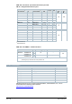
GDB..
AC 24 V ~ /
DC 24…48 V
⎓
141.9E 161.9E ─
AC 24 V ~ /
DC 24 V
⎓
─ ─ 161.9E/MO
AC 100…240 V ~ 341.9E ─ ─
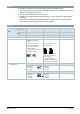
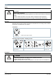
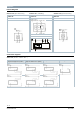
Combination with 6-port control ball
valves
Rotary direction “counter-clockwise” (ccw)
Y = 0 V Flow A ‒ C = 100% (0°)
Y = 5 V closed (45°)
Y = 10 V Flow B ‒ C = 100% (90°)
Rotary direction “clockwise” (cw)
Y = 0 V Flow B ‒ C = 100% (0°)
Y = 5 V closed (45°)
Y = 10 V Flow A ‒ C = 100% (90°)
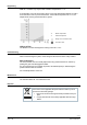
Position indication: Mechanical Rotary angle position indication by a position indicator/hand lever.
Position indication: Electrical Output voltage U = DC 0/2...10 V is generated proportional to
the rotary angle.
U depends on the rotary direction of the DIL switch setting.
Self-adaptation of linear span When self-adaptation is active, the actuator automatically
determines the mechanical end positions of the linear span.
Manual adjustment The rotary actuator can be manually adjusted by pressing the gear train disengagement button.
Rotary angle limitation The rotary angle of the shaft adapter can be limited mechanically with a set screw.
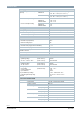
Modbus RTU (RS-485), not
galvanically isolated
Setpoint 0...100 %
valve position
Actual value 0...100 % for
valve position
Override control Open /
Close / Min / Max / Stop
Setpoint monitoring and
backup mode
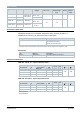
Technical design/mechanical design
Housing
The housing consists essentially of flame retardant, non brominated, non chlorinated glass
fibre reinforced plastic.
0°
45°
A
C
B
A
C
B
A
C
B
G
D
.
.
9
E
_
Z
0
5