
Data Sheet for Product


11 / 12
CE1N3547en_e Siemens
2021-10-20 Smart Infrastructure
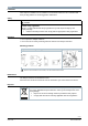
Diagrams
Internal diagrams
The VAV compact controller is supplied with two prewired connecting and communication
cables.
G..B181..KN
Dp
(G) (CE+) (CE-)
1 1 2
(G0)
2
3547G01
Tool
Tool = Configuration and maintenance interface
(Series E and later: 7-pin connector)
Power supply and communication cables
Core designation
Core color
Terminal code
Description
Cable 1: Power / black sheathing
1
red (RD)
G
System voltage AC 24 V
2
black (BK)
G0
System neutral AC 24 V
Cable 2: Communication / green sheathing
1
red (RD)
CE+
KNX CE+
2
black (BK)
CE-
KNX CE+
Note
The operating voltage at terminals G and G0 must comply with the requirements under
SELV or PELV.
Safety transformers with twofold insulation as per EN 61558 required; they must be designed
to be on 100 % of the time.
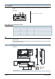
Dimensions
G..B181.1E..
Measurements in mm
min. 100
min.
200
min. 80
min. 6
8 20
ø7
2
5
180
X
8 - 16 mm
12.8 mm
15 mm
3547M01
14 x 12
X =
4.15
71
26.5
87
158
137
Ø 3...8
43
41.3
61
9.6