OpenAirTM VAV compact controller KNX/PL-Link G..B181.
Issued by Siemens Switzerland Ltd Smart Infrastructure Global Headquarters Theilerstrasse 1a 6300 Zug Switzerland Tel. +41 58-724 24 24 www.siemens.com/buildingtechnologies © Siemens Switzerland Ltd, 2019 Technical specifications and availability subject to change without notice. 2 / 46 Siemens Smart Infrastructure VAV compact controller KNX/PL-Link G..B181.
Table of contents 1 Introduction..........................................................................................4 1.1 Revision history .....................................................................................4 1.2 Before you start .....................................................................................4 1.3 Objectives of this basic documentation...................................................5 1.4 References .....................................................
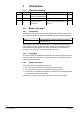
1 Introduction 1.1 Revision history Version 2.5 Date Changes 25.10.2021 Update for Series H Removal of outdated parts 2.0 23.03.2017 Update for Series G 1.0 26.02.2016 EU and RCM Conformity, European Directive 2012/19/EU 1.2 Before you start 1.2.1 Trademarks Section Pages 8 Technical data, 38 10 Environmental compatibility and 42 disposal Trademarks used in this document are listed together with their legal owners below.
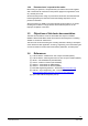
1.2.4 Document use / request to the reader Before using our products, it is important that you read the documents supplied with or ordered at the same time as the products (equipment, applications, tools etc.) carefully and in full. We assume that persons using our products and documents are authorized and trained appropriately and have the technical knowledge required to use our products as intended.
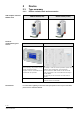
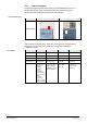
VAV compact controller KNX/PL-Link Tools for commissioning and service 2 Device 2.1 Type summary 2.1.1 Device variants, tools and accessories GDB181.1E/KN (5 Nm) GLB181.1E/KN (10 Nm) AST20 ACS931 / ACS941 The handheld tool AST20 can be used for status monitoring, VAV parameter setting, and bus configuration setting. It supports a Service and an OEM access level with PIN code protection.
2.1.2 Selection guide for all types 7 / 46 Siemens Smart Infrastructure VAV compact controller KNX/PL-Link G..B181.
2.1.3 Version summary Each VAV Compact Controller has a product series identification which can be found in the top right corner of the product label. The product series gives information about significant hardware or firmware changes. Version identification Version Series E Series F and later Identification VAV Compact Controllers series G and later are designed for using ETS device profile v2.x, however ETS device profile v1.x is supported for backward compatibility reasons.
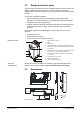
2.2 Design and device parts The VAV compact controllers consist of a differential pressure sensor, actuator and digitally configurable control electronics. They are intended for mounting on damper shafts of a minimum length of 30 mm. They consist of base and 2-sectional housing. Components contained in the base: • Steel base plate with damper drive shaft fixing for different drive shaft diameters / cross-sectional areas (cf. section 2.
2.4 Human-machine interface User interaction with the VAV compact controllers’ human-machine interface (HMI) (multicolor LED and push-button) is described below, cf. also section 6.3.1.
Internal diagrams 2.5 The VAV compact controllers are supplied with two prewired connecting and communication cables.
2.6 Measuring principle A measuring device for acquiring the differential pressure – usually a measuring cross, measuring orifice or Venturi tube in the airflow – represents the basis for air volume flow measurement. Differential pressure sensor The air volume flow is measured indirectly with a differential pressure sensor. Since the measured value is the differential pressure Dp, the air flow is derived from this value using the VAV box characteristic.
Application 3 Functionality / application 3.1 Fields of application VAV compact controllers are primarily used for controlling a variable or constant air volume flow.
Demand-controlled ventilation (DCV) 3.2.2 Example: AHU control optimization In combination with a suitable supervisory room controller, an AHU control optimization algorithm can be run using the actual value of the damper position feedback signal. The control of variable speed drives (VSDs) can be accomplished by various means. Below depicted is DC 0...
4 Electrical and mechanical installation 4.1 Mechanical installation / mounting Mounting and mounting limitations For mounting and limitations on mounting (location / position), consulting the mounting instruction M3547 ([2]) is mandatory. Environmental conditions The permissible ambient temperature and ambient humidity must be observed. Manual control The actuator may only be manually operated when separated from power supply.
4.2 Electrical installation / cabling 4.2.1 Power supply cabling Permissible cable lengths and crosssectional areas The permissible cable lengths and cross-sectional areas depend on the actuators’ current draw and the voltage drop on the connecting lines to the actuators. The necessary cable lengths can be determined from the following chart or with the help of the formulas. Cf. also to technical data in section 8.
Formula for cable length The following formula can be used to calculate the maximum cable lengths.
Parameterization 5 Parameterization and operating modes 5.1 Settings and user interaction 5.1.1 Device parameters The OEM generally provides the basic configuration to VAV Compact Controllers, esp. the parameter Vn. The basic configuration is independent of the system environment where the VAV Compact Controllers are to be used. For parameter setting, configuration and maintenance tools as described in section 0 are available.
Calculation formulas 5.1.2 The parameters are based on the following formulas: Calculation of Vn (Δpnom = nominal pressure) 𝑉𝑛 = √ 300 [𝑃𝑎] ∆𝑝𝑛𝑜𝑚 [𝑃𝑎] 300 Pa is the upper limit of the operating range of the differential pressure sensor. The nominal pressure is the differential pressure in the VAV box at a given nominal volume flow, determined by the OEM specification. Min. and max. volume flows (Vmin / Vmax) Actual relative flow as function of setpoint and min. / max. limits 𝑉𝑚𝑖𝑛 [%] = 𝑚𝑖𝑛.
5.2 Configuration and maintenance tools Configuration and retrieval of device parameters can be accomplished with the following tools: • Using the PC software ACS941 or ACS931 together with the interface converter AST22 via the configuration and maintenance interface of the VAV Compact Controller or • Using the handheld tool AST20. 5.2.
5.3 Setting examples 5.3.1 Symbols and parameters ) and without point (V) shall have the same Volume symbols with “point” ( V meaning, i.e., they all shall refer to volume flows.
Setting example A2 VAV ratio control, 20 % constant excess supply air volume flow (positive pressure in the room) Supply air Supervisory controller VAV compact controller Extract air V m in V m ax V m in V m ax 20 % 0% 80 % 100 % 0% 0% 60 % 100 % Reference signal: Ysupply_air = 35 %, Yextract_air = Ysupply_air - 20 % = 15 % Result: Vsupply_air = 35 %, Vextract_air = 15 % Supply air controller Extract air controller V max V min V max V min V 120 120 100 100 80 60 60 40
5.3.3 Min/max control by the VAV compact controller When setting the minimum / maximum air volume flow in the VAV compact controller, the supervisory controller must be set to Vmin= 0 % und Vmax = 100 %. With this setting, the supervisory controller reference signal for both the supply air and extract air controller is the same. Thus, supply air / extract air control with a single reference signal is possible.
Setting example B2 VAV ratio control, 20 % constant excess supply air volume flow (positive pressure in the room) Supply air Supervisory controller VAV compact controller Extract air V m in V m ax V m in V m ax 0% 20 % 100 % 80 % 0% 0% 100 % 60 % Reference signal: Ysupply_air = Yextract_air = 25 % Result: Vsupply_air = 35 %, Vextract_air = 15 % Supply air controller Extract air controller V max V min V max V min V 120 120 100 100 80 60 60 40 40 V 100 100 80 80
5.3.4 Master/Slave operating mode To control supply air and extract air in KNX LTE-mode environments (Synco 700 Series C or newer), master/slave operating mode is required. In this mode, the actual value signal of the master controller (supply air) is the reference signal for the slave controller (extract air), cf. also section 6.2.2.
Setting example C2 VAV ratio control, 20 % constant excess supply air volume flow (positive pressure in the room) Supervisory controller VAV compact controller Supply air (Master) Extract air (Slave) V m in V m ax V m in V m ax 0% 20 % 100 % 80 % 0% -20 % 100 % 80 % Reference signal: Ymaster = 25 % Result: Vmaster = 35 %, Vslave = 15 % Supply air controller (Master) V max V min Extract air controller (Slave) V max V min V 120 120 100 100 80 60 60 40 40 V 100 100
Preconditions 6 Engineering and commissioning 6.1 Fundamentals 6.1.1 System environments For this chapter, sound knowledge about KNX networks and, depending on the systems environment, sufficient knowledge about the ETS software, ACS790 or Desigo ABT Site are presupposed.
6.2 Engineering 6.2.1 KNX S-mode engineering Certified KNX product The VAV compact controllers are certified KNX devices. For engineering and commissioning, the ETS software is used. The parameters and S-mode datapoints are documented in chapter Fehler! Verweisquelle konnte nicht gefunden werden.. Obtaining the KNX product data The required product data (*.vd5 or *.knxprod) can be downloaded from the Siemens website and imported into the ETS device catalog.
6.2.3 Desigo PL-Link engineering Engineering in Desigo PL-Link environments is accomplished with the Desigo ABT component ABT (Automated Building Tool). The webserver-based tool SSA (Setup and Service Assistant) is used for datapoint tests during commissioning. Plug&play commissioning To enable “plug&play” commissioning with Desigo PL-Link, the recommended engineering workflow has to be followed. At the core of this workflow is the preparation of the supervisory VAV-enabled automation station (e.g. PCX3.
6.3 Commissioning 6.3.1 Preconditions Commissioning requirements Type and number of parameters that can be set may vary. Prior to commissioning, all VAV compact controllers must be mounted according to the mounting instruction M3547 as well as all other devices as per the corresponding mounting instructions. All devices must be connected to the power supply and bus cabling. Power supply and bus cabling must be tested.
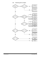
6.3.3 KNX LTE-mode commissioning VAV compact controllers, KNX LTE-mode controller and operating units are connected to the power supply. Refresh, and then open the ACS790 device list. → variant 1 (with collected address labels) 1. Select a VAV compact controller from the device list by ID (IDs are collected during mounting), 2. Double click the selected row to open the dialog box “Address assignment”, or → variant 2 1.
7 Safety and EMC optimization 7.1 Safety notes This section contains general regulations and the regulations for mains and operating voltage. It also provides important information regarding your own safety and that of the entire plant. Safety note The warning triangle to the left means that observance of all relevant regulations and notes is mandatory. If ignored, injury to persons or damage to property may result.
Operating voltage AC 24 V With regard to AC 24 V operating voltage, the following regulations must be complied with: Regulation Operating voltage AC 24 V Specification on AC 24 V transformers The operating voltage must comply with the requirements for SELV or PELV: • Permissible deviation of AC 24 V nominal voltage at the actuators: +/–20 % • Safety isolating transformers as per EN 61558, with double insulation, designed for 100 % on time to power SELV or PELV circuits • Determine the transformer’s output
7.3 Running cable in a duct Cable types Notes on EMC optimization Make sure to separate high-interference cables from equipment susceptible to interference.
8 Power supply AC 24 V Technical data Operating voltage / frequency AC 24 V ±20 % or AC 24 V class 2 (US) / 50/60 Hz (SELV/PELV) G (core 1, red) and Power consumption at G0 (core 2, black) Damper actuator Actuator holds 1 VA/0.5 W Actuator rotates 3 VA/2.
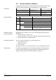
9 Datapoints and function description 9.1 Device Parameters (ACS931 / ACS941 / AST20) Parameter Range Description Factory setting Setpoint 0..100% Setpoint to VAV controller. 0% → Vmin N/A 100% → Vmax Actual position 0..100% Damper position, depends on setting for position adaptation N/A Actual Flow abs. 0..65’535 m3/h Actual volume flow in m3/h or l/s N/A Actual Flow % 0..100% Actual volume flow relative to Vnom in % N/A Actual pressure 0..
9.2 Engineering tool parameters 9.2.1 ETS Parameters Parameter Range Description Factory settings VAV / POS VAV: setpoint = volume flow 0…100% VAV Tab card “standard” Operating mode POS: setpoint = damper position 0…100% Adaptive positioning On / Off Adaption of actual (if mech. limited) opening range to position feedback 0...100% Off Off = No adaptation / On = Pos. adaptation Altitude / Correction factor for diff.
Nr. Name in ETS 9.3 S-mode group objects 9.3.1 Group objects list Object function Flags Data point type KNX Range C R W T U ID DPT_Name Format Unit 1 Fault information Transmit 1 1 0 1 0 219.001 _AlarmInfo 6 Byte --- [0...255 ] = Log Nr. [0...2] = Alarm priority [0...14] = Application area [0...4] = Error class [0...7] = Attributes [0...7] = Alarm status 2 Fault state Transmit 1 1 0 1 0 1.
9.3.2 1 Fault information Group objects description If group object #3 ”fault transmission” is set to “on”, the following faults can be transmitted if they occur. In that case, group object #2 value changes to “alarm”. Error Group obj. #1 * Description Resolution Device jammed XX 00 0A 03 0C 05 Target position can’t be reached due to blockage.
9.4 Alarms in LTE mode (ACS790) The following alarms are available in ACS790. Alarm ID Alarm text Description What to do 0 No alarm 5020 Communication error Backup mode entered • Check connection to room controller / thermostat • Resolved when new setpoint is received 90 Diff. pressure sensor error Internal sensor error • Check pressure tubes and nozzles for dirt • Restart device • Problem persists: Contact customer support 91 Diff.
9.5 Parameter and function description 9.5.1 Vnom (nominal volume flow) [m3/h or l/s] VAV boxes are ordered through an OEM according to this nominal volume flow and min. / max. volume flow settings. The maximum volume flow for ventilating a room / zone can’t be higher than the nominal volume flow. Often the maximum volume flow is lower than Vnom for potential future expansions of volume flows. 9.5.
9.5.5 Adaptive positioning 9.5.5.1 Function For VAV boxes and air dampers with an opening range smaller than 0...90°, the position setpoint and feedback signal can be adapted to 0...100%. • Adaptive positioning off: Position control / feedback relative to 0°…90°, →Example: 0° → 0%, 18° → 20%, 81° → 90% etc. • Adaptive positioning on: Position control / feedback relative to the mechanical lower / upper endstops which are determined in an adaptation run.
9.5.6 Device Jam • If an actuator can’t reach a target position due to a mechanical failure or an angle limitation screw, a device jam alarm is thrown as ETS error, see “Group objects description”. • The device jam is detected ca. 30s after the effective mechanical end stop (when lying before the target end stop) is reached. • After 30..35s the motor stops and an alarm/status message is sent over the bus if configured accordingly.
9.6 Communication object priorities The communication objects are prioritized as listed in the table below. An override signal is active until it is disabled or the HMI/tool is disconnected from the VAV compact controller. The backup gets disabled when a new setpoint is received or a power reset is done.
10 General notes Environmental compatibility and disposal The products were developed and manufactured by using environmentally compatible materials and by complying with environmental standards. For disposal, please remember the following at the end of product life or in case of defects: • The products consist of plastics and materials such as steel, ferrite magnetic core, etc. and must not be disposed of together with domestic waste; this applies particularly to the printed circuit boards.
Issued by Siemens Switzerland Ltd Smart Infrastructure Global Headquarters Theilerstrasse 1a 6300 Zug Switzerland Tel. +41 58-724 24 24 www.siemens.com/buildingtechnologies © Siemens Switzerland Ltd, 2019 Technical specifications and availability subject to change without notice. 46 / 46 Siemens Smart Infrastructure VAV compact controller KNX/PL-Link G..B181.