
Basic Documentation

35 / 42
Siemens VAV Compact Controller Modbus RTU A6V10631862_en--_e
Smart Infrastructure 2021-10-26
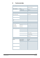
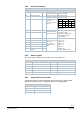
9.2.3 Device information
Reg.
Name
R/W
Value
Example
Device information
1281
Factory Index
R
Two bytes, each
coding an ASCII char.
00 5A → 00 “Z”
Device is of Series “Z”
1282
Factory Date HWord
R
Two bytes, the lower
coding the Year (hex)
Read 1282 → 000F
Read 1283 → 0418
HWord
LWord
--
YY
MM
DD
Hex
00
0F
04
18
Dec
00
15
04
24
→ Device was manufactured
24 April, 2015
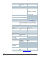
1283
Factory Date LWord
R
High byte: coding the
month (hex)
Low byte: coding the
day (hex)
1284
Factory SeqNo HWord
R
Hword + LWord =
HEX-representation
of Sequence number:
Read 1284 → 000A
Read 1285 → A206
AA206(hex) → 696838 (dec)
→ Device has sequence
number 696838
1285
Factory SeqNo HWord
R
1409
TypeASN [Char_16..1]
R
Each register: Two
bytes, each coding an
ASCII char.
ASN is coded
beginning with reg.
1409
Example:
0x47 44 = GD
0x42 31 = B1
0x38 31 = 81
0x2E 31 = .1
0x45 2F = E/
0x4D 4F= MO
→ ASN is GDB181.1E/MO
1410
TypeASN
1411
TypeASN
1412
TypeASN
1413
TypeASN
1414
TypeASN
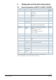
9.2.4 Status register
The status register indicates the True/False state of the listed items.
Status
Bit 00
1 = Local override
Bit 06
1 = Adaptation run done
Bit 01
1 = Backup mode active
Bit 07
1 = Adaptation run in progress
Bit 02
1 = Sensor comm. fault
Bit 08
1 = Reserved
Bit 03
1 = Sensor tubes crossed
Bit 09
1 = Reserved
Bit 04
1 = Device jammed
Bit 10
1 = Self-test passed
Bit 05
1 = Nom. lifetime exceeded
Bit 11
1 = Invalid configuration
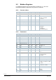
9.2.5 Supported function codes
The following function codes are supported. For function code 16 “Write multiple
register”, the limitation of max. 120 register within one message applies.
Function codes
03 (0x03)
Read Holding Registers
04 (0x04)
Read Input Registers
06 (0x06)
Write Single Register
16 (0x10)
Write Multiple registers