
User Manual


8/12 2019-01-14 M4634 74 319 0402 0 H
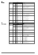
de
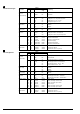
Kabelbezeichnungen
Anschluss
Kabel
Bedeutung
Code
Nr.
Farbe
Abkür-
zung
Antriebe
AC 24 V
(Kabel schwarz)
G
1
rot
RD
System Potential AC 24 V
G0
2
schwarz
BK
Systemnull
Y1
6
violett
VT
Stellsignal AC 0 V "Uhrzeigersinn"
Y2
7
orange
OG
Stellsignal AC 0 V "Gegenuhrzeigersinn"
Y
8
grau
GY
Stellsignal DC 0...10 V, 0...35 V
U
9
rosa
PK
Stellungsanzeige DC 0...10 V
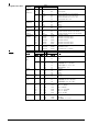
Modbus
Ref
6
violett
VT
Reference
(Kabel blau)
+
8
grau
GY
Modbus +
-
9
rosa
PK
Modbus -
KNX
CE+
1
rot
RD
KNX CE+
(Kabel grün)
CE-
2
schwarz
BK
KNX CE-
Antriebe
N
4
blau
BU
Nullleiter
AC 230 V
Y1
6
schwarz
BK
Stellsignal AC230 V, Uhrzeigersinn
Y2
7
weiss
WH
Stellsignal AC 230 V,Gegenuhrzeigersinn
Hilfsschalter
Q11
S1
grau/rot
GYRD
Schalter A Eingang
Q12
S2
grau/blau
GYBU
Schalter A Ruhekontakt
Q14
S3
grau/rosa
GYPK
Schalter A Schliesskontakt
Q21
S4
schwarz/rot
BKRD
Schalter B Eingang
Q22
S5
schwarz/blau
BKBU
Schalter B Ruhekontakt
Q24
S6
schwarz/rosa
BKPK
Schalter B Schliesskontakt
Rückführ-
a
P1
weiss/rot
WHRD
Potentiometer 0...100 % (P1-P2)
potentimeter
b
P2
weiss/blau
WHBU
Potentiometer Abgriff
c
P3
weiss/rosa
WHPK
Potentiometer 100...0 % (P3-P2)
en
Wire designations
Connection
Cable
Meaning
Code
No.
Color
Abbreviation
AC 24 V
Actuators
(black cable)
G
1
red
RD
System potential AC 24 V
G0
2
black
BK
System neutral
Y1
6
purple
VT
Actuating signal AC 0 V "clockwise"
Y2
7
orange
OG
Actuating signal AC 0 V "anticlockwise"
Y
8
gray
GY
Actuating signal DC 0...10 V, 0...35 V
U
9
pink
PK
Position indication DC 0...10 V
Modbus
Ref
6
purple
VT
Reference
(blue cable)
+
8
gray
GY
Modbus +
-
9
pink
PK
Modbus -
KNX
CE+
1
red
RD
KNX CE+
(green cable)
CE-
2
black
BK
KNX CE-
AC 230 V
N
4
blue
BU
Neutral
Actuators
Y1
6
black
BK
Actuating signal AC 230 V, "clockwise"
Y2
7
white
WH
Actuating signal AC 230 V, "anticlockwise"
Auxiliary switch
Q11
S1
gray/red
GYRD
Switch A input
Q12
S2
gray/blue
GYBU
Switch A normally closed contact
Q14
S3
gray/pink
GYPK
Switch A normally open contact
Q21
S4
black/red
BKRD
Switch B input
Q22
S5
black/blue
BKBU
Switch B normally closed contact
Q24
S6
black/pink
BKPK
Switch B normally open contact
Feedback
a
P1
white/red
WHRD
Potentiometer 0...100 % (P1-P2)
potentiometer
b
P2
white/blue
WHBU
Potentiometer pick-off
c
P3
white/pink
WHPK
Potentiometer 100...0 % (P3-P2)