
Basic Documentation


38/44
Siemens Rotary actuators with spring return GCA…1 CE1Z4613en
Building Technologies Diagrams 2017-05-26
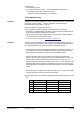
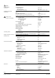
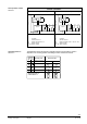
9.2 Cable labeling
All wires are color-coded and labeled.
Pin
Cable
Meaning
Code
No.
Color Abbreviation
Actuators G 1 red RD System potential AC 24 V/DC 24…48 V
AC 24 V G0
2 black BK
System neutral
DC 24…48 V Y1 6 purple VT
Pos. signal AC 0 V/AC 24 V/DC 24…48 V
"Open“
Y2 7 orange OG
Pos. signal AC 0 V/AC 24 V/DC 24…48 V
"Close“
Y 8 grey GY Pos. signal DC 0...10 V, 0...35 V
U 9 pink PK Position indication DC 0...10 V
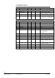
Modbus types REF 6 violet VT Reference (Modbus RTU)
+
8 gray GY Bus + (Modbus RTU)
- 9 pink PK Bus - (Modbus RTU)
Actuators L 3 brown BN Phase AC 230 V
AC 230 V N 4 blue BU Neutral conductor
Auxiliary switch Q11 S1 grey/red GY RD Switch A input
Q12 S2 grey/blue GY BU Switch A normally-closed contact
Q14 S3 grey/pink GY PK Switch A normally-open contact
Q21 S4 black/red BK RD Switch B input
Q22 S5 black/blue BK BU Switch B normally-closed contact
Q24 S6 black/pink BK PK Switch B normally-open contact
Feedback a P1 white/red WH RD Potentiometer 0...100 % (P1-P2)
potentiometer b P2 white/blue WH BU Potentiometer pick-off
c P3 white/pink WH PK Potentiometer 100...0 % (P3-P2)
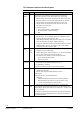
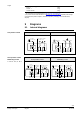
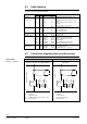
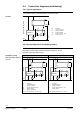
9.3 Connection diagrams (two-pos./three-pos.)
GCA121.1, GCA126.1. GCA321.1, GCA326.1
AC 24 V / DC 24…48 V (SELV/PELV) AC 230 V
4613A03
(Q1)
N
S2 S3 S5 S6
S1 S4
Y
1
2
SP
SN
AC 24 V / DC 24...48 V
GCA12..1
(Q2)
4613A04
(Q1)
N
S2 S3 S5 S6
S1 S4
Y
3
4
L
N
AC 230 V
(Q2)
GCA32..1
N Controller
Y Actuator GCA12..1
SP System potential AC 24 V / DC 24…48 V
SN System neutral
N Controller
Y Actuator GCA32..1
L Live conductor AC 230 V
N Neutral conductor
Two-position
GCA12..1, GCA32..1