
Basic Documentation


22/44
Siemens Rotary actuators with spring return GCA…1 CE1Z4613en
Building Technologies Wiring notes 2017-05-26
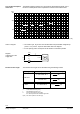
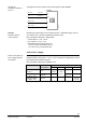
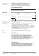
The diagram applies to AC/DC 24 V and shows the permissible line length L as a
function of consumption P and as a parameter of the line cross-sectional area.
300
200
100
0
0
8 16 24 32
L [m]
P
[VA, W]
2.5 mm²
1.5 mm²1 mm²
0.5 mm²
0.75 mm²
4614D01en
∂ The values in [VA, W] on the P-axis are allocated to the permissible voltage drops
(ΧU/2U = 4 %) on line L as per the above table and to the diagram.
∂ C is the primary power consumption for all actuators connected in parallel.
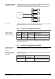
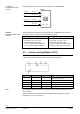
U
Χ
U/2
Χ
U/2
R
L
R
L
L
L
U
,Χ
U
4614D09
M
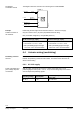
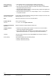
The maximum line length can be calculated using the following formula.
Operating voltage Perm. voltage drop / line Formula for line length
AC/DC 24 V
4 % of AC/DC 24 V
L =
P
A1313 ∂
Ζm∴
1 % of DC 10 V
L =
I(DC)
A5.47 ∂
Ζm∴
AC 230 V 2 % of AC 230 V
L = 46 ∂
P
A1313 ∂
Ζm∴
A Cross-sectional area in [mm
2
]
L Permissible line length in [m]
P Power consumption in [VA] or [W];
the value is printed on the actuator's type field.
I(DC) DC current portion in line G0 in [A]
Line length/consumption
AC/DC 24 V
Notes on diagram
Diagram:
Voltage drop on the
supply lines
Formula for line length