
Basic Documentation


40/44
Siemens Rotary actuators with spring return GCA…1 CE1Z4613en
Building Technologies Diagrams 2017-05-26
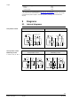
9.4 Connection diagrams (modulating)
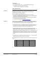
9.4.1 Typical application
The controller output is connected directly to the actuator input.
4613A06
(Y)
N
S2 S3 S5 S6
S1 S4
Y
(G0)
1 8
2 9
SP
AC 24 V / DC 24...48 V
P
(G)
GCA16..1
SN
N Controller
Y Actuator GCA16..1
P Position indication
SP System potential
AC 24 V / DC 24…48 V
SN System neutral
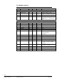
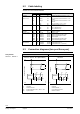
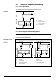
9.4.2 Special diagram for modulating control
The following diagram enables different operating states of the actuator depending on
the position of the changeover switch with switch contacts K1, K2, K3
(see table of operating states below).
AC 24 V (SELV/PELV) DC 24…48 V (SELV/PELV)
4613A07
(Y)
N
S2 S3 S5 S6
S1 S4
Y
(G0)
1 8
2 9
SP
AC 24 V
P
(G)
GCA16..1
K1 K3
D
SN
K2
4613A08
(Y)
N
S2 S3 S5 S6
S1 S4
Y
(G0)
1 8
2 9
SP
DC 24...48 V
P
(G)
GCA16..1
K1 K3
SN
K2
N Controller
Y Actuator GCA16..1
P Position indication
SP System potential AC 24 V
SN System neutral
D Diode (e.g. R4000)
K1...K3 Switch contacts (10 V / 0.1 mA)
N Controller
Y Actuator GCA16..1
P Position indication
SP System potential DC 24…48 V
SN System neutral
K1...K3 Switch contacts (10 V / 0.1 mA)
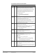
GCA16..1
Modulating control,
fully open, fully shut
with
GCA16..1