
Basic Documentation


17/44
Siemens Rotary actuators with spring return GCA…1 CE1Z4613en
Building Technologies Engineering notes 2017-05-26
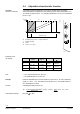
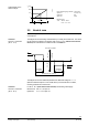
The following regulations apply to these operating voltages:
Regulation
Operating voltage
AC 24 V
DC 24…48 V
The operating voltage must comply with the
requirements for SELV or PELV:
∂ Permissible deviation of AC 24 V / DC 24…48 V
nominal voltage at the actuators: +/– 20 %
Operating voltage
AC 230 V
∂ Permissible deviation of AC 230 V nominal
voltage at the actuators: +/–10 %
Specification on AC 24 V
transformers
∂ Safety isolating transformers as per EN 61 558,
with double insulation, designed for 100 % duty
to supply SELV or PELV circuits.
∂ Determine the transformer’s power consumption
by adding up the power consumption in VA for
all actuators used.
∂ The capacity used from the transformer should
amount to at least 50 % of the nominal load for
efficiency reasons (power efficiency).
∂ The nominal capacity of the transformer must be
at least 25 VA. For smaller transformers, the
ratio between voltage at idle time to voltage at
full load is unsatisfactory (> + 20 %).
Specification for DC 24…48 V
supply
∂ Determine the supply by adding up the power
consumption in W for all actuators used.
Fuse of
AC 24 V
DC 24…48 V operating voltage
Transformers, secondary side or DC supply:
∂ According to the effective load of all connected
devices
∂ Line G (system potential) must always be fused
∂ Where required, line G0 also (system neutral)
Fuse of AC 230 V mains voltage
Transformers, primary side as per the applicable
installation regulations of the respective country.
4.2 Device-specific regulations
Safety for the devices is ensured by (among other aspects):
∂ Supply of AC 24 V / DC 24…48 V extra-low voltage as per SELV or PELV
∂ Double insulation between AC 230 V mains voltage and SELV/PELV circuits
∂ Mount max. two actuators on the same damper shaft.
Use the mounting bracket to secure the second actuator also
(see accessories in section 2.2).
Apply only mains voltage or only safety extra-low voltage to the switching outputs of
auxiliary switches A and B. Mixed operation is not permissible. Operation using various
phases is not permissible.
Consider the potentiometer's electric data to indicate the damper position via the
external circuit.
Up to 10 actuators of the same device type can be electrical parallel wired. Cable
length and cable cross section have to be respected.
See chapter 6 “wiring notes” for more information.
Do not open the actuator!
The actuator is maintenance-free. Only the manufacturer may conduct any repair work.
Operating voltage
AC 24 V
DC 24…48 V
, AC 230 V
Device safety
Mechanical parallel
connection of actuators
Auxiliary switches A, B
Feedback potentio-
meter for position
indication
Electrical parallel
connection of actuators
Caution,
maintenance