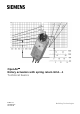
OpenAir Rotary actuators with spring return GCA…1 Technical basics Edition 2.
/44 Siemens Building Technologies Rotary actuators with spring return GCA…1 CE1Z4613en 2017-05-26
Contents 1 Introduction ................................................................................................... 5 1.1 Revision history............................................................................................. 5 1.2 About this document ..................................................................................... 5 1.3 Document contents ....................................................................................... 6 2 Spring return actuators ...........
7.1 General checks ...........................................................................................27 7.2 Electrical functional check ...........................................................................27 7.3 Modbus .......................................................................................................29 7.3.1 HMI – Human-machine interface ................................................................ 29 7.3.2 Push button addressing ..............................
1 Introduction 1.1 Revision history Changes Date Chapter Pages 2.2, 2.3.1 6, 7 2.6 9 8 27 11.1 33 2.2, 11.2 6, 34 Electrical parallel connection of actuators 4.2 15 Permissible line lengths and crosssectional areas 6.1 19 10 32 Dimensions (2 x 33.75) 11.1 33 Referenced documents (Note STEP) 11.2 34 Wiring notes 6 19…23 Powerpack (two actuators) Setting and operating elements Technical data (Dimensions) 04.12.
1.3 Document contents This document contains technical fundamentals on the rotary actuators with spring return of type series GCA...
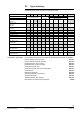
2.2 Type summary The following table shows the options for the actuator types. GCA... 121.1E 126.1E 321.1E 326.1E 131.1E 135.1E 161.1E Control type Operating voltage AC 24 V DC 24…48 V AC 24 V DC 24 V Operating voltage AC 230 V Positioning signal Y DC 0...10 V DC 0...35 V with characteristic function Uo, ΧU X X X X 164.1E 166.1E Modulating control Standard version Three-position control Two-position control 163.
2.3 Description of functions 2.3.1 Description of functions for GCA...1 The functions are listed in a table and are assigned to the respective modes of control. Type Mode of control Positioning signal with adjustable characteristic function GCA12..1 / GCA32..1 GMA13..1 Two-position Three-position - GCA16..1 GCA161.1E/MO Modulating Modbus RTU Y = DC 0...35 V with offset Uo = 0...5 V and span ΧU = 2...
2.3.2 Function description supplement for GCA16..1 The following information applies to modulating actuators. Characteristic function (GCA163.1, GCA164.1 Offset Uo and span ΧU can be adjusted using two potentiometers (see section 3.4 "Adjustable characteristic function"). The maximum permissible input voltage (Uo + ΧU) is DC 35 V. Application Actuators featuring this function can be used for the following applications: ∂ Dampers with a rotary angle limitation, for instance in the 0...
2.5 Mechanical design Brief description The electromotoric GCA...1 electronic actuators are available for two-position, threeposition, modulating and networked control with spring return. The nominal torque is 18 Nm. The actuator's connecting cables are prewired. Housing Robust, light-weight full metal housing made of die-cast aluminum. The housing guarantees a long actuator life even under harsh environmental conditions.
2.
3 Introduction Technical design This chapter discusses the following topics: ∂ Drive motor and spring return ∂ Adjustable auxiliary switches ∂ Adjustable characteristic function (setpoint signal, DC 0...35 V) ∂ Control characteristics by including the neutral zone 3.1 Drive motor and spring return Drive motor The brushless DC motor allows for accurate speed control, torque supervision to protect the actuator and dampers, and provides a reliable spring return function.
3.3 Electrical functions Auxiliary switches and positioning signals The illustration below shows the relationship between the angular rotation, the adjustable switching points for auxiliary switches A and B, and the positioning signal.
3.4 A modulating positioning signal DC 0..35 V from a controller drives the actuator. The angular rotation is proportional to the positioning signal. Using potentiometer "Uo", you can set the offset for DC 0...5 V, and with potentiometer " ΧU", you can set the span for DC 2...30 V. Ys [%] 100 1) 4) 3) 2) 4637D04 Actuators GCA163.1, GCA164.1 Adjustable characteristic function ΧU 5 2 10 15 20 30 0 2 5 10 30 35 Y [V] 25 Uo 0 1 2 ΧU (max.
Y S [%] 100 4637D02 Characteristic for the above example Max. positioning range Ysmax = Span Ys = Offset Uo = Span ΧU = 50 0 2 Uo U min 3.5 10 18 Y [V] 100 % (95°) 50 % (47.5°) 2V 16 V Effective span ΧUw = Umax – Umin = 10 V - 2 V = 8 V ΧU (16 V) U max Neutral zone For modulating actuators, note the control characteristic for the selected switch-on point of the setpoint. Actuators GCA161.1, GCA166.1 (DC 0...10 V) The diagram shows the setting characteristics by including the neutral zone.
4 Engineering notes Introduction Carefully study the basics of the control systems used before proceeding to the sections below, and pay special attention to all safety-related information. Intended use Use these actuators in a system only for applications as described in the basic system documentation of the control systems used. Additionally, note the actuator-specific properties and conditions as described in this chapter and in chapter 8 "Technical data". 4.
, Operating voltage AC 24 V DC 24…48 V AC 230 V The following regulations apply to these operating voltages: Operating voltage AC 24 V DC 24…48 V Operating voltage AC 230 V Specification on AC 24 V transformers Specification for DC 24…48 V supply Fuse of AC 24 V DC 24…48 V operating voltage Fuse of AC 230 V mains voltage 4.
4.3 Notes on EMC optimization Running cables in a duct Make sure to separate high-interference cables from equipment susceptible to interference. Cable types ∂ Cables emitting interference: Cable segregation ∂ Both cable types can be routed in the same cable ducting, but in different compartments. ∂ If ducting with three closed sides and a partition is not available, separate the interference-emitting cables from other cables by a minimum of 150 mm or route in separate ducting.
The following chart (example EMCO) allows for determining the total torque for this air damper type.
5 Mounting notes Mounting instructions All information and steps to properly prepare and mount the actuator are available in the mounting instructions 4 319 2615 0 (M4613) delivered with the actuator. The shaft adapter as well as all other individual parts are not premounted, as the actuator components are put together differently depending on either clockwise or counterclockwise rotation of the damper shaft and damper shaft length. Refer to section 2.5 Mechanical design.
6 Introduction Wiring notes Prior to wiring, study all information in the following sections: ∂ "Safety notes" in section 4.1 ∂ "Device-specific regulations" in section 4.2 ∂ "Notes on EMC optimization" in section 4.3 ∂ "Connection Diagrams" in chapter 9, and the ∂ HVAC plant diagram. ∂ This chapter is written for AC/DC 24 V and AC 230 V (Information for AC 24…48 V on inquiry) 6.
Line length/consumption AC/DC 24 V The diagram applies to AC/DC 24 V and shows the permissible line length L as a function of consumption P and as a parameter of the line cross-sectional area. 4614D01en L [m] 300 200 2.5 mm² 0.75 mm² 100 1 mm² 1.5 mm² 0.5 mm² P 0 0 Notes on diagram Diagram: Voltage drop on the supply lines 8 16 ∂ The values in [VA, W] on the P-axis are allocated to the permissible voltage drops (ΧU/2U = 4 %) on line L as per the above table and to the diagram.
The following sections show how to determine the permissible line length and crosssectional areas for the various actuators based on examples. The examples for actuators connected in parallel apply to the following arrangement: G0 G L2 A1 L2 A2 L2 A3 L2 A4 G0 G L1 G0 G Controller G0 L1 G G0 G G0 G Assumption The line resistances of L2 are equal and can be ignored for L1. Separately calculate the permissible line lengths L2 for other connections (ring, star-like). 6.
P&I diagram: Conduction currents The diagram shows the currents in the connecting lines for one actuator. GCA13..1 2 6 7 Example: Parallel connection of two actuators 0.3 A 0.2 A 0V AC 0.3 A DC 0.2 A AC/DC 24 V AC/DC 24 V G G0 M Y1 Y2 Determining the line lengths for two actuators GCA13..1 and AC 24 V supply. Only the currents in line 1 (G) and 2 (G0) determine the line sizing. Max. permissible voltage drop = 4 % per line (total 8 %).
P&I diagram: Conduction currents at AC 24 V The diagram shows the currents in the connecting lines for one actuator. GCA16..1 1 2 AC 24 V AC 0.3 A 0V AC 0.3 A G G0 M 9 Example: Parallel connection of four actuators Y DC 0...10 V 4613G08en 8 DC 0...10 V U Determining the line lengths for four actuators GCA16..1 at AC 24 V supply. Only the AC currents in line 1 (G) and 2 (G0) determine the line sizing. Max. permissible voltage drop = 4 % per line.
P&I diagram: Conduction currents at DC 24 V The diagram shows the currents in the connecting lines for one actuator. GCA16..1 1 2 DC 24 V DC 0.2 A 0V DC 0.2 A DC 0...10 V DC 0.1 mA G G0 M DC 1 mA 9 Example: Parallel connection of four actuators Y U (DC 0...10 V) 4613G10en 8 Determining the line lengths for four actuators GCA16..1 at DC 24 V supply. Only the DC currents in line 1 (G) and 2 (G0) determine the line sizing. Line 2 (G0): (max. voltage drop 1 %) Line 1 (G): (max.
7 References Commissioning notes All information necessary for commissioning is contained in the following: ∂ This document ("Technical basics" Z4613en) ∂ Mounting instructions 4 319 2615 0 (M4613) ∂ HVAC plant diagram 7.1 General checks Environmental conditions Check to ensure that all permissible values as contained in chapter 8 "Technical data" are observed. Mechanical check ∂ Check for proper mounting and to ensure that all mechanical settings correspond to the plant-specific requirements.
Rotary movement: Modulating control GCA16..1 ∂ When applying a DC 10 V input signal, the actuator must turn from 0° ⇑ 90° / 90° ⇑ 0° (or to the end position of the rotary angle limitation). ∂ After interrupting the operating voltage, the actuator must return to the mechanical zero position (spring return function). ∂ After interrupting positioning signal Y, but while operating voltage is still supplied, the actuator returns to the zero position. ∂ When the actuator moves from 0...
Push button operation 7.3 Modbus 7.3.1 HMI – Human-machine interface Activity Push-button operation Confirmation Display current address Press button < 1s 1-digits: red (starting with lowest address digit) 10-digits: green 100-digits: orange If termination is switched on, LED flashes 1x blue after address display Example: 124 = 4x red, 2x green, 1x orange Turn bus termination on / off turn on 1.press 3x LED flashing and flickering stops (termination mode) 2.
Resetting the device by push button 1. 2. 3. 4. Press button for >10s → LED starts flashing orange. Release button while LED still flashes → LED keeps flashing for 3s. If the button is pressed within these 3s, the reset is cancelled. After those 3s → LED shines red (reset), then the device restarts. 7.3.2 Push button addressing The Modbus address can be set without a separate tool by using push-button and LED. To display the current address, press button <1s.
Set address “5”: 1. Enter addressing mode 2. Set 1- digit: Press button 5-times → LED flashes green per button press Store address: press button until LED shines red → address is stored and displayed 1x for confirmation 7.3.3 Commissioning Workflow 1 The devices are especially designed for using the Climatix push-button configuration as described in document A3975 1). The bus configuration can alternatively be parameterized by the local HMI, cf. page 29.
7.3.4 Modbus registers Reg. Name R/W Unit Scaling Range / enumeration Process Values 1 Setpoint RW % 0.01 0..100 2 Override control RW -- -- 0 = Off / 1 = Open / 2 = Close 3 = Stop / 4 = GoToMin / 5 = GoToMax 3 Actual position R % 256 Command RW -- 0.01 0..
Reg. Name R/W Value Example Device information 1281 Factory Index R Two bytes, each 00 5A ⇓ 00 “Z” coding an ASCII char.
7.3.5 Parameter and function description Function Reg. Description Override control 2 The actuator can be operated in override control for commissioning / maintenance purposes or system-wide functions (e.g. night-cooling). ∂ Manual override: When the gear disengagement is used to freely adjust the damper position, a mechanical jam will be detected if a mismatch between setpoint and actual position persists for more than 10s.
8 Supply, AC 24 V / DC 24…48 V (SELV/PELV) for GCA12..1, GCA13..1, GCA16..1.. Technical data Operating voltage AC Frequency Operating voltage DC GCA161.1E/MO Safety extra-low voltage (SELV) or Protective extra-low voltage (PELV) as per Requirements for external safety isolating transformer (100% duty) Supply line fuse Power consumption: Running Running Holding Holding AC 24 V °20 % or AC 24 V class 2 (US) 50 / 60 Hz DC 24…48 V °20 % DC 24 V °20 % HD 384 as per EN 61 558 max.
Protected against faulty wiring max. AC 24 V / DC 24…48 V Position indicator for GCA16..1 Output signal (wires 9-2) Output voltage U Max. output current Protected against faulty wiring DC 0...10 V DC ° 1 mA max. AC 24 V / DC 24…48 V Feedback potentiometer for GCA135.1 Change of resistance (wires P1-P2) Load Max. sliding contact current Permissible voltage at potentiometer (SELV/PELV) Insulation resistance between potentiometer and housing 0...
Weight Weight without packaging GCA1..1 GCA32..1 GCA161.1E/MO 2.0 kg 2.1 kg 2.2 kg 1) The documents can be downloaded from http://siemens.com/bt/download The product environmental declaration contains data on environmentally compatible product design and assessments (RoHS compliance, materials composition, packaging, environmental benefit, disposal). 2) GCA12..1 GCA32..1 AC 24 V / DC 24…48 V AC 230 V AC 24...230 V / 6 (2) A DC 12...
9.2 Cable labeling All wires are color-coded and labeled. Code No. Cable Color Abbreviation G G0 Y1 1 2 6 red black purple RD BK VT Y2 7 orange OG Y U REF + - 8 9 6 8 9 grey pink violet gray pink GY PK VT GY PK System potential AC 24 V/DC 24…48 V System neutral Pos. signal AC 0 V/AC 24 V/DC 24…48 V "Open“ Pos. signal AC 0 V/AC 24 V/DC 24…48 V "Close“ Pos. signal DC 0...10 V, 0...35 V Position indication DC 0...
Three-position control GCA13..1 GCA131.1, GCA135.1 AC 24 V (SELV/PELV) AC 24 V / DC 24…48 V (SELV/PELV) SP SP (G) Q2 6 7 N P1 P2 P3 S1 S4 GCA13..1 Q1 Q2 (Y1) (Y2) 6 N P1 P2 P3 7 S1 S4 S2 S3 S5 S6 GCA13..1 Y 2 S2 S3 SN N Y SP SN Q1, Q2 Operating states of GCA13..1 Controller Actuator GCA13..1 System potential AC 24 V System neutral Switch contacts S5 S6 Y 1 4613A09 1 2 SN N Y SP SN Q1, Q2 4613A10 AC 24 V (Y2) AC 24 V/DC 24...
9.4 Connection diagrams (modulating) 9.4.1 Typical application The controller output is connected directly to the actuator input. GCA16..1 SP (Y) 1 (G0) N 8 S1 S4 9 S2 S3 S5 S6 GCA16..1 2 Y SN P SN Controller Actuator GCA16..1 Position indication System potential AC 24 V / DC 24…48 V System neutral N Y P SP 4613A06 AC 24 V / DC 24...48 V (G) 9.4.
Switch contacts Operating state K3 Control operation K2 Fully open *) K1 Fully closed Mounting position for actuators GCA16..1 Note GCA163.1, GCA164.1 Direction of rotary 4613T02en Operating states of GCA16..1 *) Actuators with adjustable characteristic function: Full opening cannot be reached (depending on Uo, ΧU) in this position (switch contact K2). 9.5 Connection diagrams (networked) 9.5.1 Typical application GCA161.
11 Chapter contents Appendix This chapter contains: ∂ Actuator dimensions ∂ Referenced documents 11.
11.2 Referenced documents Purpose of this listing The previous chapters contain all information relevant to safety and project-specific requirements, mounting, wiring, and commissioning of actuators. Documents and standards The following list contains all documents referenced by this document on basics: ∂ Data sheets (N....) with detailed specifications ∂ Mounting instructions (M….
4 718 1406 0 Special shaft adapter ASK74.1 74 319 2946 0 Weather shield ASK75.1 (M4626.11) Standards and directives HD 384 EN 61 558 IEC/EN 61 000-6-1 IEC/EN 61 000-6-2 IEC/EN 61 000-6-3 89/336/EEC 73/23/EEC Issued by Siemens Switzerland Ltd Building Technologies Division International Headquarters Gubelstrasse 22 6301 Zug Switzerland Tel. +41 41-724 24 24 www.siemens.