
Basic Documentation


28/44
Siemens Rotary actuators with spring return GCA…1 CE1Z4613en
Building Technologies Commissioning notes 2017-05-26
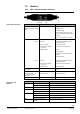
∂ When applying a DC 10 V input signal, the actuator must turn from
0° ⇑ 90° / 90° ⇑ 0° (or to the end position of the rotary angle limitation).
∂ After interrupting the operating voltage, the actuator must return to the mechanical
zero position (spring return function).
∂ After interrupting positioning signal Y, but while operating voltage is still supplied, the
actuator returns to the zero position.
∂ When the actuator moves from 0...90°, output voltage U = DC 0...10 V is generated
as a position indication.
Factory setting: The potentiometers for setting the offset Uo and span ΧU are set to the
following values: Uo = 0 V, ΧU = 10 V.
Specify the values set for Uo and ΧU in the plant papers.
Check of output voltage U:
∂ U = DC 0...10 V for angular rotation 90°.
Measures resistance changes while the actuator turns.
∂ Switchover of the auxiliary switch contacts "A" and "B" as soon as the actuator
reaches the respective switching positions.
∂ Set the setting shafts (part of the delivery) to the desired value by means of the
adjustment tool (see section 3.2, "Angular range and mechanical limitation”).
The angle values are valid only for the zero position of the actuator and when no
current is applied.
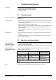
The auxiliary switches have the following settings:
∂ Switch A: Switchover point at 5°
∂ Switch B: Switchover point at 85°
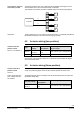
Rotary movement:
Modulating control
GCA16..1
Characteristic function
GCA163.1, GCA164.1
Note
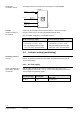
Position indicator
GCA16..1
Feedback potentiometer
GCA132.1
Auxiliary switches
A and B
Important
Factory setting