
Basic Documentation


23/44
Siemens Rotary actuators with spring return GCA…1 CE1Z4613en
Building Technologies Wiring notes 2017-05-26
The following sections show how to determine the permissible line length and cross-
sectional areas for the various actuators based on examples.
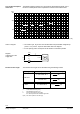
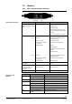
The examples for actuators connected in parallel apply to the following arrangement:
L1
L2 A1
L2
L2
A2
L2 A3
A4
L1
G0
G0
G0
G0
G0
G0
G
G
G
G
G
G
Controller
4614S01en
The line resistances of L2 are equal and can be ignored for L1. Separately calculate the
permissible line lengths L2 for other connections (ring, star-like).
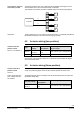
6.2 Actuator wiring (two-position)
Type
Operating
voltage
Power
consumption
Perm. voltage drop for line
1 (G) and 2 (G0)
GCA12..1
AC 24 V
DC 24 V
7 VA
4 W
ΧU/U = max. 8 % (4 % each per line)
GCA32..1 AC 230 V 8 VA
ΧU/U = max. 4 % (2 % each per line)
Use the table or the formulas in section 6.1 to determine the permissible line lengths
and cross-sectional areas.
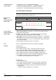
6.3 Actuator wiring (three-position)
Three-position actuators are supplied AC/DC 24 V via the supply lines 1 (G) and
2 (G0). The positioning signal current of about 8 mA is supplied via lines 6 and 7.
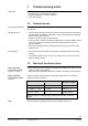
The table shows the power consumption used to size the actuator lines as well as the
permissible voltage drop.
Operating voltage
Power
consumption
Perm. voltage drop for line
1 (G), 2 (G0), 6 (Y1), 7 (Y2)
AC 24 V
DC 24 V
7 VA
4 W
ΧU/U = max. 8 % (4 % each per line)
Line length for actuators
connected in parallel
Assumption
Actuators with two-
position control
GCA12..1 and GCA32..1
Actuators with three-
position control
GCA13..1
Power consumption and
perm. voltage drop with
one actuator