
Operating Instructions


2 Parameters
2.2 List of parameters
SINAMICS G120 CU230P-2 Control Units
178 List Manual (LH9), 04/2014, A5E33838102B AA
Description: Sets the configuration of the controller for the DC link voltage (Vdc controller) in the U/f operating mode.
Value: 0: Inhib Vdc ctrl
1: Enable Vdc_max controller
2: Enable Vdc_min controller (kinetic buffering)
3: Enable Vdc_min controller and Vdc_max controller
Note: For high input voltages (p0210), the following settings can improve the degree of ruggedness of the Vdc_max
controller:
- Set the input voltage as low as possible, and in so doing, avoid A07401 (p0210).
- set the rounding times (p1130, p1136).
- Increase the ramp-down times (p1121).
- Reduce the integral time of the controller (p1291), factor 0.5.
- Activate the Vdc correction in the current controller (p1810.1 = 1) or reduce the derivative action time of the
controller (p1292, factor 0.5).
In this case, we generally recommend to use vector control (p1300 = 20) (Vdc controller, see p1240).
The following measures are suitable to improve the Vdc_min controller:
- Optimize the Vdc_min controller (see p1287).
- Activate the Vdc correction in the current controller (p1810.1 = 1).
If a braking resistor is connected to the DC link (p0219 > 0), then the Vdc_max control is automatically deactivated.
Description: Displays the switch-in level for the Vdc_max controller.
If p1294 = 0 (automatic sensing of the switch-in level = off), then the following applies:
r1282 = 1.15 * sqrt(2) * p0210 (supply voltage)
If p1294 = 1 (automatic sensing of the switch-in level = on), then the following applies:
r1282 = Vdc_max - 50.0 V (Vdc_max: Overvoltage threshold of the power unit)
r1282 = Vdc_max - 25.0 V (for 230 V power units)
Notice: If the activation level of the Vdc_max controller is already exceeded in the deactivated state (pulse inhibit) by the DC
link voltage, then the controller can be automatically deactivated (see F07401), so that the drive is not accelerated
the next time that it is activated.
Note: The Vdc_max controller is not switched back off until the DC-link voltage falls below the threshold 0.95 * r1282 and
the controller output is zero.
Description: Sets the dynamic factor for the DC link voltage controller (Vdc_max controller).
100% means that p1290, p1291, and p1292 (gain, integral time, and rate time) are used in accordance with their
basic settings and on the basis of a theoretical controller optimization.
If subsequent optimization is required, this can be carried out using the dynamic factor. In this case, p1290, p1291,
and p1292 are weighted with the dynamic factor p1283.
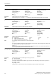
p1280[0...n] Vdc controller configuration (U/f) / Vdc_ctr config U/f
PM240
PM330
Access level: 3 Calculated: - Data type: Integer16
Can be changed: U, T Scaling: - Dyn. index: DDS, p0180
Units group: - Unit selection: - Func. diagram: 6300, 6320
Min Max Factory setting
0 3 1
r1282 Vdc_max controller switch-in level (U/f) / Vdc_max on_level
PM230
PM240, PM330
Access level: 3 Calculated: - Data type: FloatingPoint32
Can be changed: - Scaling: p2001 Dyn. index: -
Units group: - Unit selection: - Func. diagram: 6320
Min Max Factory setting
- [V] - [V] - [V]
p1283[0...n] Vdc_max controller dynamic factor (U/f) / Vdc_max dyn_factor
PM230
PM240, PM330
Access level: 3 Calculated: p0340 = 1,3,4 Data type: FloatingPoint32
Can be changed: U, T Scaling: - Dyn. index: DDS, p0180
Units group: - Unit selection: - Func. diagram: 6320
Min Max Factory setting
1 [%] 10000 [%] 100 [%]